
By default Cisco ACI Leaf switches consider every VLAN tag on a particular switch to identify a particular EPG.
Recall from my earlier tutorials, that Cisco ACI does not use VLAN tags to identify VLANs in the traditional sense, but rather it looks at a VLAN tag on an incoming frame to determine what source End Point Group (EPG) is to be used in determining the policy for this frame.
This means that if you needed to use say VLAN tag 1000 to identify EPG1 when traffic arrives at interface Ethernet 1/21, but also use VLAN tag 1000 to identify EPG2 if traffic arrives on interface Ethernet 1/22, the default settings will need to be changed.
I recently I had a situation where traffic had to be tunneled through a transparent device (an IPS), so each interface of the device was allocated to a different EPG and different Bridge Domains. The problem was, the same VLAN has to be used on the ingress side as on the egress side, so both EPGs had to be allocated the same VLAN mapping. The customer had already tried configuring the ports, but kept getting a “Configuration
failed for … due to Encap Already Used in Another EPG” error, so I looked to use the Per Port VLAN feature to rescue them.
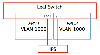
Physical Layout of IPS and Leaf Switch
It turned out that the configuration was not quite as straightforward as I expected. Here is what I did:
First I created a VLAN Scope Policy – or as Cisco has poorly named it, a L2 Interface Policy.
| Note: The following menu sequences are for an admin user operating in Advanced mode. >+ means right-click and choose.. |
FABRIC > ACCESS POLICIES > Policies > Interface Policies > Policies > L2 Interface >+ Create L2 Interface Policy.
Name: PerPort-VLAN.Scope
Scope: Port Local Scope
Then I created two VLAN Pools. I had initially tried to use the same VLAN Pool, the same Physical Domain and the same Access Port Policy Groups (APPGs) for each of the two interfaces, but it seems that the L2 Interface Policy requires that when applied to two different EPGs on the same switch, those two EPGs must be associated with two different Physical Domains, and each domain linked to a different VLAN Pool. If anyone can show me any official Cisco documentation that states this fact, I’d be really grateful as I am to dpita who posted this on his blog and a more readable version on the Cisco Support forum. The ACI help page does tell us that each EPG must be in a different Bridge Domain, but mentions nothing about requiring different VLAN Pools or physical domains. Good one Cisco!
So I will get on with it and create the VLAN Pools:
FABRIC > ACCESS POLICIES > Pools > VLAN >+ Create VLAN Pool
Name: AllVLANs-VLAN.Pool
Allocation Mode: Static
Encap Blocks: (+) VLAN 1–VLAN 4094
And another to fulfill the separate VLAN Pool requirement
FABRIC > ACCESS POLICIES > Pools > VLAN >+ Create VLAN Pool
Name: PerPortVLANs-VLAN.Pool
Allocation Mode: Static
Encap Blocks: (+) VLAN 1–VLAN 4094
Since Domains can only be linked to a single VLAN Pool, clearly two Physical Domains will be required too, and each Domain linked to its respective VLAN Pool,
FABRIC > ACCESS POLICIES > Physical and External Domains > Physical Domains >+ Create Physical Domain
Name: AllVLANs-PhysDom
VLAN Pool: (+) AllVLANs-VLAN.Pool
FABRIC > ACCESS POLICIES > Physical and External Domains > Physical Domains >+ Create Physical Domain
Name: PerPortVLANs-PhysDom
VLAN Pool: (+) PerPortVLANs-VLAN.Pool
To keep the separation complete, I also suggest creating two AEPs, although this not strictly necessary – I could have just used one AEP and added both Physical Domains
FABRIC > ACCESS POLICIES > Global Policies> Attachable Access Entity Profiles >+ Create Attachable Access Entity Profile
Name: AllVLANs-AEP
Domain: (+) AllVLANs-VLAN.PhysDom
FABRIC > ACCESS POLICIES > Global Policies> Attachable Access Entity Profiles >+ Create Attachable Access Entity Profile
Name: PerPortVLANs-AEP
Domain: (+) PerPortVLANs-PhysDom
To link these VLAN Pools to interfaces I had to create two Interface Policy Groups – in my case the devices were single attached, so I created two Access Port Policy Groups
FABRIC > ACCESS POLICIES > Interface Policies> Policy Groups >+ Create Access Port Policy Group
Name: AllVLANs-APPG
Attached Entity Profile: AllVLANs-AEP
FABRIC > ACCESS POLICIES > Interface Policies> Policy Groups >+ Create Access Port Policy Group
Name: PPVLAN.PerPortVLANs-APPG
L2 Interface Policy: PerPort-VLAN.Scope
Attached Entity Profile: PerPortVLANs-AEP
Of course, if I was a CLI jockey I would have avoided all of the GUI clicking by issuing the commands:
configure
  vlan-domain AllVLANs-VLAN.Dom
    vlan 1-4094
    exit
  vlan-domain PerPortVLANs-VLAN.Dom
    vlan 1-4094
    exit
  vlan-domain phys type phys
    exit

  template policy-group AllVLANs-APPG
    vlan-domain member AllVLANs-VLAN.Dom
    exit
  template policy-group PPVLAN.PerPortVLANs-APPG
    vlan-domain member PerPortVLANs-VLAN.Dom
    switchport vlan scope local
    exit
and the VLAN Pools, Physical (and L2 and L3) Domains and AEPs would have all been created for me, albeit with each VLAN Pool and Domain being given a name that ends with VLAN.Dom, and an AEP with a name beginning with __ui_ and which can never be deleted from the GUI should I need to do so later. Oh and two identical L2 Interface polices also beginning with the accursed __ui_
But I digress.
Of course these Access Port Policy Groups had to be assigned to the relevant ports, in my case there were interfaces Ethernet 1/21 and 1/22 on Leaf 101. I had already created a Leaf Switch Profile named Leaf101-LeafProf and linked it to its matching Interface Profile called (of course) Leaf101-IntProf.
All I had to do now was add two more Interface Selectors to the Leaf101-IntProf
Interface Profile.
FABRIC > ACCESS POLICIES > Interface Policies> Interface Profiles > Leaf101-IntProf >+ Create Access Port Selector
Name: 1:21
Interface IDs: 1/21
Interface Policy Group: AllVLANs-APPG
FABRIC > ACCESS POLICIES > Interface Policies> Interface Profiles > Leaf101-IntProf >+ Create Access Port Selector
Name: 1:22
Interface IDs: 1/22
Interface Policy Group: PPVLAN.PerPortVLANs-APPG
And of course the alternative version for the click-challenged:
  #This section is already configured
  leaf-profile Leaf101-LeafProf
    leaf-group Leaf101
      leaf 101
      exit
    leaf-interface-profile Leaf101-IntProf
    exit
  #End of already configured section

  leaf-interface-profile Leaf101-IntProf
    leaf-interface-group 1:21
      interface ethernet 1/21
      policy-group AllVLANs-APPG
      exit
    leaf-interface-group 1:22
      interface ethernet 1/22
      policy-group PPVLAN.PerPortVLANs-APPG
      exit
    exit
With the Access Policies now completed, I could now configure the two EPGs with the same VLAN ID (I was using VLAN 1000) back in the Tenant area. The EPGs had been created earlier with the creative names of EPG1 and EPG2. In this case each EPG had its own Bridge Domain and both BDs were linked to the same VRF. First EPG1 configuration:
TENANT > Tenant TenantName > Application Profiles > Tenant-AP > Application EPGs > EPG1 > Domains (VMs and Bare-Metals) >+ Add Physical Domain Association
Physical Domain Profile: AllVLANs-PhysDom
TENANT > Tenant TenantName > Application Profiles > Tenant-AP > Application EPGs > EPG1 > Static Ports >+ Deploy Static EPG on PC, VPC, or interface
Path Type: Port
Path: Pod-1/Node-101/eth1/21
Port Encap (…): VLAN 1000
And then EPG2
TENANT > Tenant TenantName > Application Profiles > Tenant-AP > Application EPGs > EPG1 > Domains (VMs and Bare-Metals) >+ Add Physical Domain Association
Physical Domain Profile: PerPortVLANs-PhysDom
TENANT > Tenant TenantName > Application Profiles > Tenant-AP > Application EPGs > EPG1 > Static Ports >+ Deploy Static EPG on PC, VPC, or interface
Path Type: Port
Path: Pod-1/Node-101/eth1/22
Port Encap (…): VLAN 1000
Or…
  leaf 101
    interface ethernet 1/21
      switchport trunk allowed vlan 1000 tenant TenantName application Tenant-AP epg EPG1
      exit
    interface ethernet 1/22
      switchport trunk allowed vlan 1000 tenant TenantName application Tenant-AP epg EPG2
      exit
    exit
  exit
At this point both EPG1 and EPG2 were happily sending and receiving frames tagged with VLAN 1000 and no traffic was leakingbetween the two EPGs. And to complete the picture, here’s the CLI version of the Tenant config:
  tenant TenantName
    vrf context VRF1
      exit
    bridge-domain BD1
      no unicast routing
      vrf member VRF1
      exit
    bridge-domain BD2
      no unicast routing
      vrf member VRF1
      exit
    application Tenant-AP
      epg EPG1
        bridge-domain member BD1
        exit
      epg EPG2
        bridge-domain member BD2
        exit
      exit
    interface bridge-domain BD1
      exit
    interface bridge-domain BD2
      exit
    exit
RedNectar

I had to deal with this out of necessity. I have a question. I think we need to do this even if we want to use the same vlan in different tenants, right?
Correct! In fact this would be a common use case.
hello Chris,
thanks for this interesting post;
about the __uixxxx objects you mentionned, Daniel wrote a quite useful post to get rid of them with simple commands via APIC bash :
Hi Joel,
Thanks for the link to Daniel’s excellent blog – I haven’t tried his script, but I’m sure it works.
Chris
Hello!
Here is Cisco Documentation on the theory of PPV. Instead of “VLAN Pool” the document uses the word “Namespace” which is what the object is actually called in the model.
“EPGs associated with different bridge domains having the same VLAN encapsulation need to be associated with different physical domains and different NameSpace pools”
http://www.cisco.com/c/en/us/td/docs/switches/datacenter/aci/apic/sw/1-x/aci-fundamentals/b_ACI-Fundamentals/networking_and___management_connectivity.html#concept_BC396E1CBB7D4687A9CBBECDDD43DE11
Thanks for that dpita – and to show us yet another inconsistency of naming within ACI. For me, of of the most challenging aspects of learning ACI has been the inconsistency of naming, particularly in the GUI. So in the document in you link, they have decided to ditch the simple term “VLAN Pool” and replace it with “Namespace Pool”, which I suspect actually means something slightly different to VLAN Pool anyway (my suspicion is that a Namespace Pool is a collective term for VLAN Pools, VXLAN Pools and possibly NVGRE Pools). Curiously, when searching for Cisco’s definition of namespace pools, the only relevant results that came back were references to the document you mentioned, and variations of it.