
An approach often used when migrating traditional IP Subnet based networks to ACI is to isolate security zones into different tenants (or VRFs), and re-deploy existing Firewalls between the tenants (or VRFs).
In this post, I’ll show you how you can enhance your ACI migration by using some ACI features that are practically impossible to implement on L3 Firewalls.
The approach is identical irrespective of whether you isolate between ACI tenants or VRFs because the isolation is at the VRF level. But for my example I’ll use two tenants. To allow communications between the tenants using an external Firewall or Router to apply policy between the tenants, I have a couple of different options.
- Use Policy Based Redirect to send traffic to to a Firewall
- Use a L3Out to connect to the Firewall
And there would be several variations of the above, even a combined approach. But for the purpose of this post, I’m going to use a L3Out to connect each interface of an external router to the tenant’s VRF.
Scope
First of all, the ground rules.
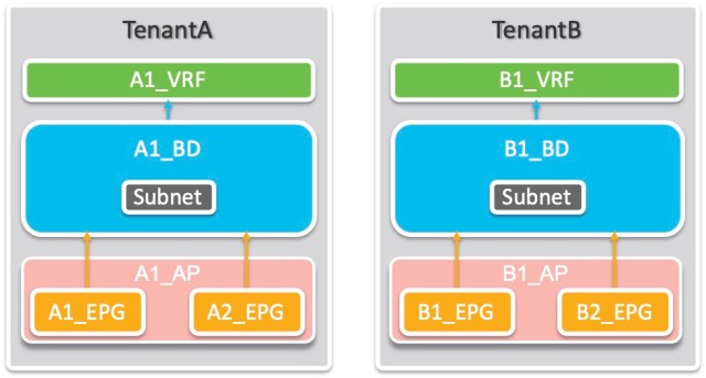
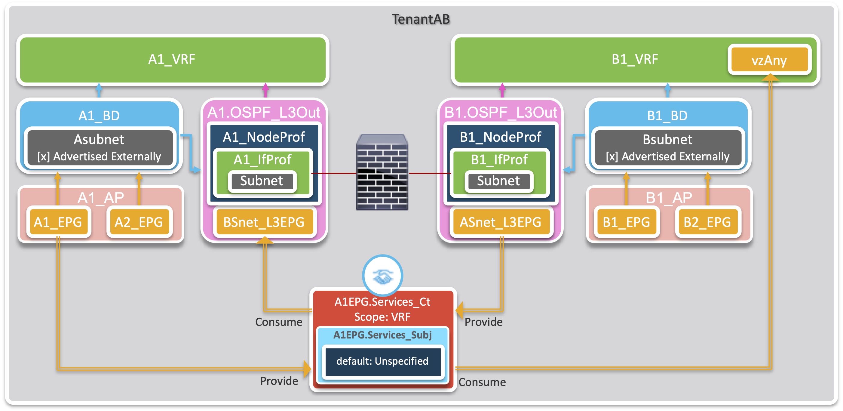
I have two tenants. TenantA and TenantB. Each has one VRF called A1_VRF and B1_VRF respectively. Each Tenant has one Bridge Domain (A1_BD and B1_BD) each with one subnet. Each tenant has one Application Profile (A1_AP and B1_AP) and each Application Profile has two EPGs, TenantA has A1_EPG and A2_EPG, and (you guessed it) TenantB has B1_EPG and B2_EPG.
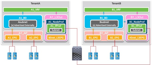
To connect to the firewall/router, each tenant has an L3Out configured and linked to the VRF. Each L3Out has an External EPG to allow traffic based on the IP addressing of the other tenant. So let’s add the L3Outs to the picture, and a little of the physical picture too.
Policy Scope
You might think that since you have a firewall in the picture, there is no need for policy. But that is not true in this scenario. You will still need ACI contracts in place to allow the endpoints in each tenant to communicate to the local firewall interface. Of course the no-brainer approach would be to allow all traffic to and from each VRF to go to the firewall. You could use the vzAny construct in the VRF and the default contract in the common tenant to do this.
No-brainer vzAny approach
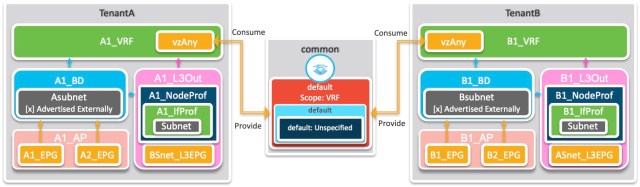
But this approach also means that you have opened up communication between every EPG in the tenant – so A1_EPG can communicate with A2_EPG. Ditto for B1_EPG and B2_EPG. And if this is what you want to do forever, then go ahead and take this approach.
But what if you now want to fine-tune your policy so that TenantB can access only the servers in A1_EPG? Or perhaps allow only B2_EPG servers access to the services in TenantA?
Because your firewall is IP based, and TenantA servers are all in the same subnet – and the same for TenantB servers – you IP based Firewall is useless to you.
This is where you can leverage the ACI EPG construct to implement policy that is impossible to implement on L3 Firewalls.
To finalise the scope of my example, I’ll scope the policy to say that all TenantB servers can access only the servers in A1_EPG. TenantA servers do not need to initiate any TCP connections to TenantB servers.
Since A1_EPG and A2_EPG are sharing a subnet, this restriction is too hard for a Firewall, so I’ll use ACI features to implement this.
Methodology
I’m going to use L3Outs in each Tenant. The L3Out will be configured to use OSPF, so the assumption is that the External Firewall is also going to dynamically learn the routes from each tenant and advertise them to the other tenant. I could have used static routes or a different routing protocol, but my lab is already set up with OSPF, so OSPF it is.
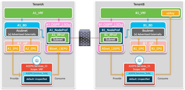
Since the firewall is still applying policy, I won’t complicate things by filtering traffic to and from the firewall, but I will create a new contract in each tenant to be used specifically for traffic to and from the firewall. This avoids any confusion later if another EPG is configured to use the common tenant’s default contract.
Note the following:
In TenantA, only A1_EPG is providing the contract, but since the contract uses the default filter (from the common tenant – which allows all traffic) the concepts of “Provide” and “Consume” have little meaning.
In TenantB, since both EPGs are able to consume any services that get past the firewall, the contract is consumed by the vzAny construct of the the VRF. If the policy should change in the future, say to restrict consumption to just one of the EPGs, the contract could easily be changed to allow this.
Another consequence of having the vzAny construct of the the VRF only consuming the contract (and NOT providing services to the contract), B1_EPG and B2_EPG are not able to communicate without a separate contract. Should you wish these EPGs to be able to communicate freely, you could configure the vzAny construct of the the VRF to consume the contract as well, or use a new contract.
In TenantA, the External EPG (BSnet_L3EPG) is based on the IP addressing of TenantB, and vice versa for the External EPG in TenantB (ASnet_L3EPG).
Although the contract in both Tenants is exactly the same, and yes, I could have configured it in the common tenant or even used the common tenant’s default contract, I wanted to emphasise in the naming and in the implementation that the contract was designed to allow the consumption of services from A1_EPG in TenantA – hence the contract is named A1EPG.Services_Ct in both tenants.
Configuration
To complete the story, I’ll add the steps required to do the L3Out configuration. I’ll assume you already have your tenants, VRFs, BDs, application profiles and EPGs configured. Similarly, I’ll assume you have created the Access Policies required to connect your external router/firewall.
My lab has the following subnets configured, and these will be used in the example:
A1_BD: 10.211.11.1/24
TenantA Router ID: 10.211.0.201
TenantA L3Out SVI: 10.211.1.201
B1_BD: 10.212.11.1/24
TenantB Router ID: 10.212.0.201
TenantB L3Out SVI: 10.212.1.201
Where the configuration is the same for both TenantA and TenantB, I’ll refer to the tenant as TenantA|B. Similarly for other names like A|B1_BD for A1_BD and B1_BD. In the following, the >+ sequence when following the menu path means right-click. >> is used to indicate the end of navigating the horizontal sub-menu and begin navigating the vertical tree menu.
Task 1: Create the contract
This will be exactly the same process on each tenant – you could indeed do this once in the common tenant and use it in both TenantA and TenantB
Tenants > TenantA|B >> Contracts > Standard >+ Create Contract
- Name: A1EPG.Services_Ct
- Scope: VRF
- [+] Subject
- Name: A1EPG.Services_Subj
- [+] Filters
- Name: common/default
Task 2: Create the L3Out
This step is the core of the config. It is a long one, and I’ll break it into sections that follow the wizard steps. By following the wizard, the Node Profiles and Interface Profiles will be named automatically, and be slightly different to my diagram above. My lab has the router connected to Leaf2201 interface 1/10 and is configured for OSPF – area 0.0.0.11 for TenantA and area 0.0.0.12 for TenantB
Tenants > TenantA|B >> Networking > L3Outs >+ Create L3Out
Wizard Step 1. Identity
- Name: A|B1.OSPF_L3Out
- VRF: A|B1_VRF
- L3 Domain: A|B_L3Dom [Recall I’ve assumed you have the access policies configured]
- [x] OSPF
- OSPF Area ID: 0.0.0.x [in my config, x=11 for TenantA and 12 for TenantB]
- Regular Area
Wizard Step 2. Nodes and Interfaces
- Interface Types
- Layer 3: SVI
- Layer 2: Port
- Nodes
- Node ID: Leaf2201
- Router ID: 10.21x.0.201 [in my config, x=1 for TenantA and 2 for TenantB]
- Loopback Address: 10.21x.0.201
- Interface: 1/10 [in my lab]
- IP Address: 10.21x.1.201 [in my config, x=1 for TenantA and 2 for TenantB]
- MTU: 1500
- Encap: VLAN
- IP Address: 24×1 [in my config, x=1 for TenantA and 2 for TenantB]
Wizard Step 3. Protocol Associations
- [x] Hide Policy
Wizard Step 4. External EPG
- Name: BSnet_L3EPG [for TenantA] ASnet_L3EPG [for TenantB]
- Provided Contract: <blank> [for TenantA] A1EPG.Services_Ct [for TenantB]
- Consumed Contract: A1EPG.Services_Ct [for TenantA] <blank> [for TenantB]
- Default EPG for all External Networks [ ] UNCHECKED
- [+] Subnets:
- IP Address: 10.212.0.0/16 [for TenantA] 10.211.0.0/16 [for TenantB]
Note that the subnets specify the range of EXTERNAL addresses – so TenantA specifies that TenantB’s subnets are permitted, and vice versa for TenantB
Task 3: Configure your BDs
You will need to modify your existing BDs in two ways to ensure each tenant’s subnet is advertised to the external router/firewall:
- Configure the subnet for each BD and check the Advertised Externally option.
Tenants > TenantA|B >> Networking > Bridge Domains > A|B1_BD > Subnets > 10.21x.11.1/24 [in my config, x=1 for TenantA and 2 for TenantB]
- [x] Advertised Externally
- Link the BD to the L3Out
Tenants > TenantA|B >> Networking > Bridge Domains > A|B1_BD >| [L3 Configurations]
- [+] Associated L3 Outs
- A|B1.OSPF_L3Out
Task 4: Apply the contracts
For my example, I’m allowing all of TenantB to use the services from TenantA but only A1_EPG is providing the service.
So, for TenantA
Tenants > TenantA >> Application Profiles > A1_AP > Application EPGs > A1_EPG > Contracts >+ Add Provided Contract
- A1EPG.Services_Ct
But, for TenantB
Tenants > TenantB >> Networking > VRFs > B1_VRF > EPG Collection for VRF
- [+] Consumed Contracts
- A1EPG.Services_Ct
That concludes the required configuration. You are ready to test.
You should find that:
- All servers in both EPGs for TenantB can access the servers in TenantA’s A1_EPG, but nothing from A2_EPG even though A1_EPG and A2_EPG servers are on the same subnet.
- This is the key finding – you have used ACI features to implement additional control above and beyond what can be achieved by using a firewall alone.
- TenantA’s EPGs can’t communicate until you configure another contract to allow them to communicate.
- TenantB’s EPGs can’t communicate until you configure another contract to allow them to communicate.
Conclusion
The whole point of this post is to show that you can easily use ACI features to implement additional control above and beyond what can be achieved by using a firewall alone.
Don’t just blindly force all traffic through a firewall without thinking about what traffic actually needs to be firewalled – you’ll reduce the load on the firewall and give yourself access to easier fine tuning in the future.
RedNectar

i see that you created a contract for every vrf, using vrf scope on both contracts. I guess if it wouldn’t be possible to create a single contract with global scope, allowing both EPGs to talk to each other. (I am thinking on a scenario where both vrfs are in the same tenant, linked by l3outs on the firewall).
Hi JDC,
Let me address your points – not necessarily in order that you made them.
If you had one tenant, two VRFs, two EPGs and each EPG linked to a different VRF, like the diagram below then it would behave exactly as the two tenant scenario in the blogpost.
Yes it WOULD be possible to create a single contract, but if configured as in the example. In fact I mention in the article:
Now back to your case. It’s the last bit of the second sentence that is the crux of the matter.
Well, yes – it would be possible. Since (in your scenario) A1_EPG is providing and vzAny of B1_VRF (and therefore B1_EPG and B2_EPG) is consuming the same contract, then if the scope of the contract was changed from VRF to global or tenant, then B1_EPG and B2_EPG would be able to consume the services of A1_EPG WITHOUT TRAVERSING THE FIREWALL. Which defeats the purpose of the firewall!

Bit long winded, but I think I’ve answered your question.