
Goodbye to VLANs. Well… not quite
2025 Update: Revised and revived in line with newer thinking and ACI v5.2+ updates
Cisco ACI Tutorial – Part 2
ACI does not use VLANs or even subnets to isolate policy groups. I’m sorry if this is a shock for you, but before I discuss how policy groups are bound by an object known as an End Point Group I’ll use this tutorial to take you through the replacement concepts for VLANS and IP addressing. The containers used by ACI to provide IP addressing isolation are the Tenant, and the VRF. Bridge Domains are used to provide multicast and broadcast isolation (similar to VLANs) and you’ll be pleased to know that we still use Subnets for IP addressing.
In this part of the tutorial I am going to take you through the configuration of the primary containers in ACI as you setup a Tenant, a VRF, two Bridge Domains and two Subnets.
TIP: |
If you have not read Cisco ACI Tutorial – Part 1, now would be a good time. It contains a diagram of the topology and some important notes about conventions used. |
First a little theory
ACI uses the concepts of Tenants, VRFs, Bridge Domains, and Subnets in a hierarchy to contain routed traffic. Note that the concept of VLANs is entirely absent. Later I will add the most important policy containment concept, End Point Groups (EPGs) to the mix.
This diagram shows the hierarchy of Tenants, VRFs, Bridge Domains, and Subnets.
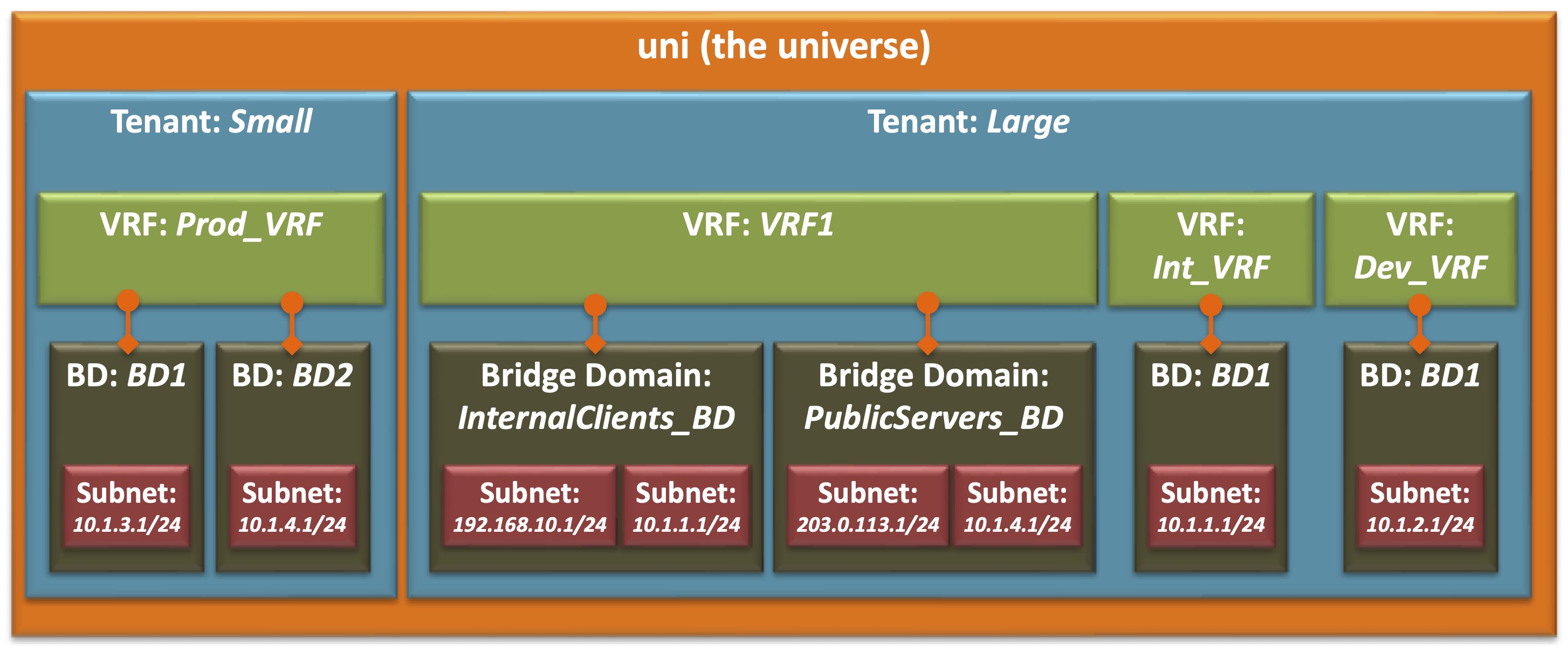
Note that some relationships are linked such as Bridge Domains, which are linked to VRFs, while others are parent-child relationships, such as Subnets, which are children of Bridge Domains which in turn are children of Tenants. Note that these relationships are also one-to many – a Tenant may have multiple VRFs, VRFs can be linked to multiple Bridge Domains, and Bridge Domains many multiple child Subnets, but a Bridge Domain can be linked to only one VRF
Note: |
Typically you will have only one Subnet per Bridge Domain, so in that sense a Bridge Domain “resembles” a VLAN, and a Subnet “resembles” a VLAN interface. |
The naming and numbering of the items also reveals some of the isolation as well. Note that the names BD1 and BD2 have been used in each Tenant, and that Tenant Large has three VRFs, two of which have an instance of the 10.1.1.1/24 subnet associated with it.
| Note: |
The subnet numbering is on purpose. 10.1.1.1/24 actually defines the Distributed Gateway address for the subnet 10.1.1.0/24, but it is convenient to use the numbering to indicate both in this diagram. |
Configuration Steps
The tenant that we are going to build in this tutorial is much simpler than the one shown in the diagram above. The following diagram represents the beginnings of the build of the tenant RedNectar
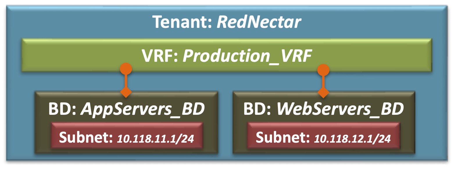
Tenant RedNectar with VRF, BDs and Subnets
Step 1: Add a new Tenant
A tenant is a logical container for application policies that enable an administrator to exercise domain-based access control. A tenant represents a unit of isolation from a policy perspective, but it does not represent a private network. Tenants can represent a customer in a service provider setting, an organization or domain in an enterprise setting, or just a convenient grouping of policies. [From ACI online help – Cisco removed online help in ACI v5.2(6)]
A Tenant is a logical container for isolating routing and switching functions. A Tenant will require at least one VRF to provide routing functionality if required, and at least one Bridge Domain to provide layer 2 isolation. [RedNectar’s Definition]
Tenants > Add Tenant
- Name: RedNectar #Or choose your own name
| Note: |
Clicking Submit or Next, and Finished is assumed since I have come to the end of the item. I almost always avoid using the Wizard steps because Wizards are magical creatures that are particularly good at hiding information. By avoiding the Wizards, you will get to know where the individual configuration items are placed. |
Step 2: Give the new Tenant a VRF
A Virtual Routing and Forwarding (VRF) object (also known as a context, an instance, or private network) contains
the Layer 2 andLayer 3 forwarding configuration for a tenant, and IP address space isolation for tenants. Each tenant can have one or more VRFs, or share one default VRF with other tenants as long as there is no overlapping IP addressing being used in the ACI fabric. [From ACI online help – Cisco removed online help in ACI v5.2(6) – I’ve corrected this definition by out the reference to layer 2]A Virtual Routing and Forwarding (VRF) object contains the Layer 3 forwarding configuration for a tenant, and IP address space isolation for tenants. Each tenant can have one or more VRFs. Although technically possible for Tenants to share a VRF in the common tenant, it is best practice to NOT share VRFs between tenants. [RedNectar’s Definition]
Tenants > RedNectar >> RedNectar > Networking > VRFs >+ Create VRF
| TIP: |
The sequence >+ in the line above means right-click and select
The Create VRF option can also be reached by clicking the Actions menu at the top right hand side of the Work Pane You can also use a drag-and-drop method of creating a VRF from the Work Pane of the Networking option in the Navigation Pane |
-
- Name: Production_VRF
- Create A Bridge Domain [ ] Unchecked
Step 3: Give the new Tenant two Bridge Domains
A bridge domain represents a Layer 2 forwarding construct within the fabric.
A bridge domain must have at least one subnet associated with it and must have a relation to a context. Bridge domains define a unique Layer 2 MAC address space and a Layer 2 flood domain if flooding is enabled. AcontextVRF defines a unique IP address space that can consist of multiple subnets. Those subnets are defined in one or more bridge domains that have a relation to the correspondingcontextVRF. [From ACI online help – Cisco removed online help in ACI v5.2(6)- I’ve corrected this definition where necessary]A Bridge Domain is a Layer 2 (broadcast) domain that defines a unique Layer 2 MAC address space and a Layer 2 flood domain if flooding is enabled. If a layer 3 service (routing between subnets) is required then the Bridge Domain must also be associated with a VRF. A Bridge Domain may contain one or more Subnets that can provide a gateway services for endpoints in associated End Point Groups. [RedNectar’s Definition]
Tenants > RedNectar >> RedNectar > Networking > Bridge Domains >+ Create Bridge Domain
-
- Name: AppServers_BD
- VRF: Production_VRF
… >+ Create Bridge Domain
-
- Name: WebServers_BD
- VRF: Production_VRF
Step 4: Give each new Bridge Domains a Subnet
A subnet defines the IP address range that can be used within the bridge domain. While a
contextVRF defines a unique layer 3 space, that space can consist of multiple subnets. These subnets are defined per bridge domain. A bridge domain can contain multiple subnets, but a subnet is contained within a single bridge domain. [From ACI online help – Cisco removed online help in ACI v5.2(6)- I’ve corrected this definition where necessary]A Subnet is defined by an IP address/mask and provides a routing gateway service for endpoints in End Point Groups that are associated to the Subnet‘s parent Bridge Domain. A Bridge Domain can contain multiple Subnets, but a Subnet is contained within a single Bridge Domain. [RedNectar’s Definition]
Tenants > RedNectar >> RedNectar > Networking > Bridge Domains > AppServers_BD > Subnets >+ Create Subnet
-
- Gateway IP: 10.118.11.1/24
Tenants > RedNectar >> RedNectar > Networking > Bridge Domains > WebServers_BD > Subnets >+ Create Subnet
-
- Gateway IP: 10.118.12.1/24
Step 5: Verify your configuration
Tenants > RedNectar >> RedNectar > Networking
A topology view of your network will appear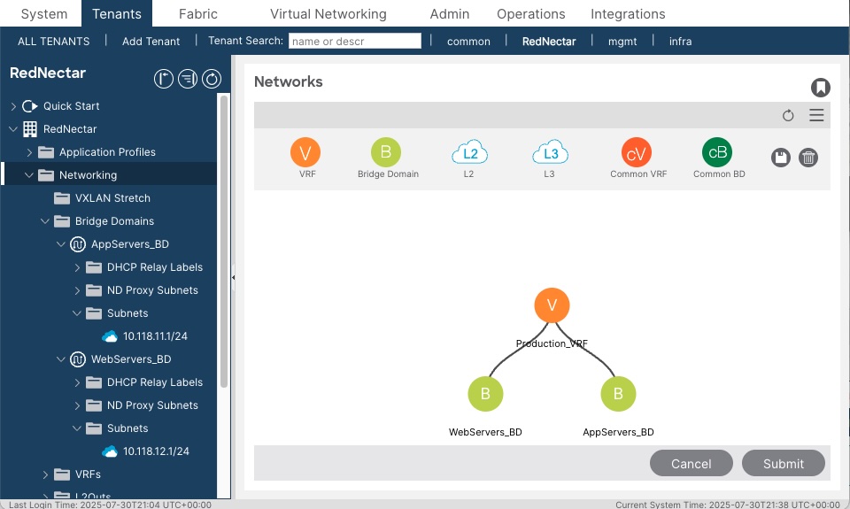
Topology view of VRF and BDsAlso navigate your way around the Navigation Pane and expand the relevant sections to verify that you have the correct IP addresses assigned,
Diagrammatically, you have built when we set out to build:
Tenant RedNectar with VRF, BDs and Subnets
Discussion
Note that you have created a structure to contain your subnets that does not involve VLANs. If you have come from a networking background, this will be a foreign concept for you. Subnets are however contained by another scope called a Bridge Domain. In many ways a Bridge Domain is similar to a VLAN, but is not a container for policy enforcement. For Policy enforcement, you will need to sing a new song for sorting server groups and policy, namely Application Profiles and End Point Groups.
RedNectar
Footnotes
| Naming Conventions: | Note also the naming convention used. You will find that I almost always give an object a descriptive name followed by an underscore followed by an identifier – such as AppServers_BD
You can read more about my philosophy of naming in this blog post. |

Pingback: Cisco ACI Tutorial 4 – The Access Policy Chain – a new “interface range” command | RedNectar's Blog
Pingback: Cisco ACI Tutorial 3 – Sing a new song for sorting server groups and policy | RedNectar's Blog
Pingback: Cisco ACI Tutorial – A Configuration Guide | RedNectar's Blog