
The Access Policy Chain – a new “interface range” command
2025 Update: This post is currently being re-written in line with newer thinking and ACI v5.2+ updates. Check back soon for the updated version
Cisco ACI Tutorial – Part 4
Since you no longer have to configure ports on individual switches, but rather configure multiple ports on multiple switches from a central controller, some concepts that were reasonably straight forward, are a little more complex in ACI. In particular, defining a range of interfaces on a switch ready to add common configuration could be achieved in Cisco IOS CLI using the interface range command. But in ACI, those interfaces may exist on multiple switches, and are configured using the ACCESS POLICIES submenu under FABRIC POLICIES.
In this part of the tutorial I’ll explain how the APIC uses the concepts of Profiles, Policies and Policy Groups to achieve something like what we might have once tried to configure (but not succeeded, because there was no way to include multiple switches in the interface range command) as:
configure terminal
 interface range switch1/eth/1/1-10, switch2/eth/1/1-10
  cdp enable
  speed 1000
I will then expand this concept to include Attachable Access Entity Profiles, Domains and VLAN Pools to expand the conceptual configuration above to also include:
switchport trunk allowed vlans 1000-1010
And of course, continue the sample configuration example.
TIP: |
If you have not read Cisco ACI Tutorial – Part #1, now would be a good time. It contains a diagram of the topology used in this tutorial and some important notes about conventions used. Similarly, you will get more familiar with the context of this tutorial if you also take a look at Parts #2 and #3 of this Cisco ACI Tutorial. |
Recall that in Part #1, I presented a table that showed the planned usage of a set of ports on my test ACI Lab. Here is is again.
| Port range | Use |
| 1/1-2 | External L3 Routers |
| 1/3-4 | External L2 Switches |
| 1/5-10 1/5-7 10Gb/s 1/8-10 1Gb/s |
Single Attached Bare Metal Hosts |
| 1/11-14 | VPCs to ESXi Hosts |
| 1/15-20 1/15-17 10Gb/s 1/18-20 1Gb/s |
Single Attached ESXi Hosts |
| 1/21-24 | VPCs to UCS B Series |
| 1/25-28 | VPCs to Bare Metal Hosts |
| 1/29-32 | Port Channels to Bare Metal Hosts |
| 1/33-40 | FEX connections |
| 1/41 | SPAN Port |
| 1/42-44 | APIC attachments |
For my example, I’ll assume that I want to prepare ports 1/5-10 on both leaf switches ready to connect to bare metal hosts (BMHs). I’ll also assume that ports 5-7 will be connected to hosts with 10Gb/s NICs, and that ports 1/8-10 will go to hosts with 1Gb/s NICs. In reality, I’d probably be connecting the hosts using a Virtual Port Channel (VPC) so to complete the example I’ll allocate ports 1/25-28 for VPCs to BMHs.
Note: |
Keeping the configuration of ports the same on pairs of switches is going to make life easier, especially if VPCs are involved. |
Switch Profiles, Switch Selectors, Interface Profiles and Access Port Selectors
As usual, I will begin with a picture.

First of all, keep in mind that the interface range concept now needs to include switch identifiers as well as slot/interface numbers, so you will see in the diagram above that there is an object known as a Switch Profile() that has at least one child entity called a Switch Selector. These two combine to define a named range of switches which are rather useless unless they are linked to at least one Interface Profile() with its associated Access Port Selector entities.
A Switch Profile can define a single (leaf) switch, or a number of switches, and this profile can be linked to a number of Interface Profiles defining a range of interfaces, and so it is a combination of the Interface Profile and the Switch Profile which is the more powerful replacement for the command:
interface range
But there is a couple of important differences between the ACI concept and the old IOS interface range
Firstly, in the ACI world, everything (including Switch/Interface ranges) is done through named objects. And when it comes to defining interfaces, each physical port can only belong to one named Access Port Selector. Any attempt to include the same port in a different Switch Profile+Selector plus Interface Profile+Access Port Selector combination will result in an error.
Which leads me to the other difference – with the IOS interface range command, the effect is transient. Once I have completed the configuration steps I need, there is no evidence in my configuration that I’d used the range construct rather than configuring each interface individually. And there would be no problem in using a command like interface range 1/1-10, do some configuration, then use the interface range 1/1-5 to modify just some of those ports.
This is not the case in the ACI world. In the ACI world, it is possible to define a named Switch Profile+Selector combination that includes all your switches, and link it to an Interface Profile that includes an Access Port Selector that defines the range of ports 1/1-10.
And once you had done this, those first 10 ports on all of your switches are stuck with congruent configuration forever (meaning if you change any one, you will change them all). In other words, the Switch Profile+Selector plus Interface Profile+Access Port Selector is NOT transient – it stays forever.
So the ACI construct is both more powerful (because you can group ports across multiple switches) and more inflexible (because these ports can be stuck in these groups, and hard to re-purpose).
To maximise flexibility, I recommend the following:
- Define one Switch Profile for each individual leaf switch in your data centre. It will have one Switch Selector that specifies that single switch.
- Define one Switch Profile for each pair of leaf switch in your data centre that will be used for VPCs. It will have two Switch Selectors each specifying one of the two switches.
- This means you now have two kinds of Switch Profiles, one for Virtual Port Channels, and one for single-attached devices.
- Define one and only one Interface Profile for each Switch Profile
- Define one Access Port Selector for every single port that you intend to use in that particular Switch Profile. In other words, DO NOT define interface ranges, like 1/1-10. Instead, define 10 Interface Selectors, each with one port. You will be happy you did the day you need to change the configuration for port 1/8 whilst leaving the others the same.
Now the the Switch Profile+Selector plus Interface Profile+Access Port Selector will need to have some policies associated with it, and this is where the concept of Interface Policy Groups comes in.
Interface Policy Groups and Interface Policies
In truth, this collective name is a little misleading – you can not define an Interface Policy Group as such, but you can define an Access Port Policy Group, or a PC Interface Policy Group or even a VPC Interface Policy Group.
Key Point: |
There are three types of Interface Policy Groups – one of these is for directly attached devices, the other two for bundled interfaces.
|
At first look, an Interface Policy Group seems like an entity to allow you to collect together a group of similar polices (known collectively as Interface Policies) in a named entity that can later be applied to a group of ports. And this is partially true, but it is much more than that, especially when it comes to Port Channel Interface Policy Groups (PCIPGs) and to Virtual Port Channel Interface Policy Groups (VPCIPGs)
The illustration below shows two Interface Policy Groups, one is an Access Port Policy Group, and the other a VPC Interface Policy Group. Each contains a set of Interface Policies that might seem appropriate to apply to ports that are intended to be used for attaching single or dual attached Bare Metal Hosts (BMHs). I hope the logic of my naming scheme and the completeness of the diagram will suffice for a full explanation of the relationships. I’ll assume you can work out what a CDP Policy called Disable-CDPPol will do.
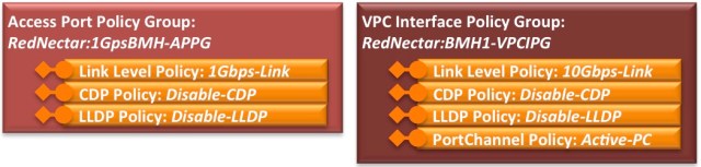
As you can see, in each of these Interface Policy Groups, an interface policy for Link Level (where link speed is defined), CDP, LLDP and for the VPC, LACP has been applied. There are currently (v1.1) ten different polices that can be placed in an Interface Policy Group.
The following diagram shows how these Interface Policy Groups are linked via the Access Port Selector to the Switch Profile+Selector plus Interface Profile+Access Port Selector discussed earlier.

Note the important role that the Access Port Selector plays in this link. It really doesn’t matter which Interface Profile a particular interface finds itself in, so long as on one hand it is linked to the correct switch identifier, and on the other hand is linked to the correct Interface Policy Group. So what is really important above is that ports 1/5-7, on Leaf Switches 101 & 102 are linked to the 10GbpsBMH-APPG
This relationship is even more important for Port Channel Interface Policy Groups and Virtual Port Channel Interface Policy Groups, because a single PCIPG or VPCIPG can only refer to a set of ports that define a single Port Channel or Virtual Port Channel in much the same away as a single port-channel interface (such as interface port-channel1) can only refer to a single port-channel in IOS or NXOS.
Let me use an example to illustrate.
Suppose you were using interfaces 1/25-28 on both Leaf Switch 101 and 102 to create VPCs to three different Bare Metal Hosts. Although each of those ports require exactly the same set of policies, and same set of VLANs (discussed later), you will need to create three VPC Interface Policy Groups – one for each VPC – you can’t use the same Interface Policy Group and expect LACP to sort out the fact that it is port 25 on each switch that connects to BMH1, port 26 on each switch that connects to BMH2, and ports 27 and 28 on each switch that connects to BMH3. Instead, as shown in the example above, each VPC Interface Policy Group has to be defined uniquely.
There is one more important piece of information that the Interface Policy Group provides. And that is the set of VLANs that are permitted on the associated ports, and this is done by linking each and every Interface Policy Group with a very strange Global Policy element known as an Attachable Access Entity Profile(*)
The VLAN containers: Attachable Access Entity Profiles, Domains and VLAN Pools
To add the AEP(*) concept to the diagram, I’ll have to stretch it a little, so use the diagram below to mentally enhance part of the the top right hand side of the diagram above.
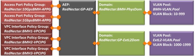
Notice first that every Interface Policy Group needs to be associated with an Attachable Access Entity Profile (AEP). Dwelling on this concept for a while helps conceptualise the name of the object. An Attachable Access Entity Profile. Or AEP (*) as it is commonly known.
With this concept in mind, you can think of an AEP as a collection point for a group of access ports, port-channels and virtual-port channels. Possibly this collection of ports have been dedicated to a single Tenant (you probably will want at least one AEP per Tenant) so I have included the Tenant’s name in the name of the AEP above – RedNectar:GP-AEP. The “GP” just means “General Purpose”, so for now just think of this AEP as a single Entity, or Entity Profile for Attachable things, like Access Ports and Port-Channels and Virtual Port-Channels. Hence – an Attachable Access Entity Profile.
But these ports also need access to a set of VLANs, which leads to the concepts of VLAN Pools and Domains. You will get a better mental picture if you think of Domains(*) as VLAN Domains, as I will explain shortly.
A VLAN Pool is nothing more than a collection of VLAN IDs assigned in blocks. And every (VLAN) Domain needs a single VLAN Pool associated with it. And every AEP can be associated with a bunch of (VLAN) Domains.
So this makes the AEP a meeting point for VLANs and ports (sorry – Attachable Access Entities) to get together and party. Any VLAN in any Domain that needs access to any port/port-channel will need to be at the party, and of course the corresponding port/port channel will also need to be present.

A more formal description of an AEP is that an AEP is a container that allows you to define which VLANs – via its relationship to Domains – are allowed to exist on which Attachable Entities (Ports/Port Channels/Virtual Port-Channels) – via its relationship to Interface Profiles
So an AEP is more or less the equivalent of:
switchport trunk allowed vlan 10-999, 1000-1999
If you wanted to specifically specifically restrict a port (or PC/VPC) to a single specific VLAN (say VLAN 100), you would need to:
- Create a VLAN Pool that had only one VLAN (VLAN 100)
- Create a Domain of the appropriate type (see below) – let’s call it VLAN100-PhysDom
- Allocate that VLAN Pool to the VLAN100-PhysDom Domain
- Create an AEP – let’s call it OneVLAN-AEP
- Allocate ONLY the VLAN100-PhysDom to OneVLAN-AEP
- Link the Interface Profile that defined the particular port (or PC/VPC) that you wished to restrict to the OneVLAN-AEP
Which would be the equivalent of (in IOS/NXOS terminology)
switchport trunk allowed vlan 100
And should you every wish to expand the AEP to allow more VLANs, you would need to either:
- Add more VLANs to the VLAN Pool; or
- Add more Domains to the AEP
A word about Domains
As I mentioned earlier, Domains(*) are a place to deposit a bunch of VLANs via a VLAN Pool. But they also serve another purpose, and that is to link the physical configuration (via the AEP) to the Logical Tenant configuration. Just how this is done depends on the type of Domain involved. And there are four type of Domains – and remember, each Domain is going to define a set of available VLANs.
- Physical Domains provide a mechanism to permit a set of VLANs on a given port (or PC/VPC) where a directly attached hosts or switch might be attached. This makes it possible to then map one of the allowed VLANs on a particular port (or PC or VPC) to a particular EPG. This is discussed more in Part #5 of this tutorial.
- VMM Domains (Vritual Machine Manager Domains) do a little more than just provide a mechanism to permit a set of VLANs on a given port (or PC/VPC) where a directly attached (e.g.) ESXi host might be attached. A VMM Domain also provides a mechanism to integrate with the related VMM (either VMware vCenter/vShield or Microsoft SCVMM as of 2015) so that the VLANs associated with the VMM can be dynamically allocated and automatically allocated to EPGs. This is discussed more in Part #5 of this tutorial.
- Layer 2 External Domains provide a mechanism to permit a set of VLANs on a given port (or PC/VPC) where a External Bridged Network (aka L2Out) connects. This makes it possible to then map one of the allowed VLANs on a particular port (or PC or VPC) to a Node Profile/Interface Profile. This is discussed more in Part #6 of this tutorial.
- Layer 3 External Domains provide a mechanism to permit a set of VLANs on a given port (or PC/VPC) where a External Routed Network (aka L3Out) connects. This makes it possible to then map one of the allowed VLANs on a particular port (or PC or VPC) to a Node Profile/Interface Profile. This is discussed more in Part #6 of this tutorial.
| TIP: |
Life will be simpler if you only configure one AEP per Tenant, (hence the naming convention used) and within each Tenant one Physical Domain, one Layer 3 External Routed Domain and a VMM Domain for each type of hypervisor. Each Domain is given a non-overlapping range of VLANs, and all Domains are linked to the Tenant’s common AEP. If you have overlapping VLANs, you’ll need a second AEP for that Tenant. |
Time to start configuring. It is going to be easier if I start by defining the re-usable general purpose objects (Interface Policies and a VLAN Pool), then a Physical Domain to hold the VLAN Pool, then move on to the physical side of things by creating an Attachable Access Entity Profile(*) then do Interface Profiles/Access Port Selectors and work back to Switch Profiles/Selectors. In other words, I will work more-or-less backwards to the sequence I used to explain the concepts.
Configuration Steps
Interface Policies will only ever need to be configured once (unless new options are added) and will be common across all Tenants.
| TIP: |
Create a standard set of Interface Policies and use my Naming Convention (I hope to write a more complete post about this in the future).
Once you have your set of Interface Policies in place, avoid using Wizards, because they may re-create duplicates of the policies you have. |
Step 1: Add new Link Level Interface Policies for 1Gbps and 10Gbps
Link Level Policy is the host interface policy, which specifies the layer 1 parameters of host facing ports. [Adapted from ACI Help]
A Link Level Interface Policy contains the Physical Layer policies applied to a port when a linked Interface Policy Group is applied to a physical interface via an Access Port Selector. [RedNectar’s Definition]
FABRIC > ACCESS POLICIES > Interface Policies > Polices > Link Level
- (+) Create Link Level Policy
- Name: 1Gbps-Link
- Speed: 1 Gbps
- Name: 1Gbps-Link
- (+) Create Link Level Policy
- Name: 10Gbps-Link
- Speed: 10 Gbps
- Name: 10Gbps-Link
Step 2: Add new CDP Interface Policies to enable/disable CDP
The CDP interface policy is primarily used to obtain protocol addresses of neighboring devices and discover the platform of those devices. CDP can also be used to display information about the interfaces your router uses. CDP is media- and protocol-independent, and runs on all Cisco-manufactured equipment including routers, bridges, access servers, and switches [From ACI Help]
A CDP Interface Policy contains the CDP policy (enabled/disabled) applied to a port when a linked Interface Policy Group is applied to a physical interface via an Access Port Selector. [RedNectar’s Definition]
FABRIC > ACCESS POLICIES > Interface Policies > Polices > CDP Interface
- (+) Create CDP Interface Policy
- Name: Enable-CDP
- Admin State: (x) Enabled
- Name: Enable-CDP
- (+) Create CDP Interface Policy
- Name: Disable-CDP
- Admin State: (x) Disabled
- Name: Disable-CDP
Step 3: Add new LLDP Interface Policies to enable/disable LLDP
The LLDP interface policy defines a common configuration that will apply to one or more LLDP interfaces. LLDP uses the logical link control (LLC) services to transmit and receive information to and from other LLDP agents. [From ACI Help]
An LLDP Interface Policy contains the LLDP policy (Tx/Rx enabled/disabled) applied to a port when a linked Interface Policy Group is applied to a physical interface via an Access Port Selector. [RedNectar’s Definition]
FABRIC > ACCESS POLICIES > Interface Policies > Polices > LLDP Interface
- (+) Create LLDP Interface Policy
- Name: Enable-LLDP
- Receive State: (x) Enabled
- Transmit State: (x) Enabled
- Name: Enable-LLDP
- (+) Create LLDP Interface Policy
- Name: Disable-LLDP
- Receive State: (x) Disabled
- Transmit State: (x) Disabled
- Name: Disable-LLDP
Step 4: Add new PortChannel Policies for LACP variations
The Port Channel policy enables you to bundle several physical ports together to form a single port channel. LACP enables a node to negotiate an automatic bundling of links by sending LACP packets to the peer node. [From ACI Help]
A PortChannel Interface Policy contains the policies to be used when bundling pairs of ports together to from a PortChannel or Virtual PortChannel. The policy is applied to a port when a linked Interface Policy Group is applied to a physical interface via an Access Port Selector. [RedNectar’s Definition]
FABRIC > ACCESS POLICIES > Interface Policies > Polices > PortChannel Policies
- (+) Create PortChannel Policy
- Name: Static-PC
- Mode: (x) Static Channel – Mode On
- Name: Static-PC
- (+) Create PortChannel Policy
- Name: ActiveLACP-PC
- Mode: (x) LACP Active
- Name: ActiveLACP-PC
- (+) Create LACP Interface Policy
- Name: PassiveLACP-PC
- Mode: (x) LACP Passive
- Name: PassiveLACP-PC
- (+) Create LACP Interface Policy
- Name: MacPinning-PC
- Mode: (x) Mac Pinning
- Name: MacPinning-PC
VLAN Pools can be considered re-usable objects, but I would advise creating a new VLAN Pool for every Domain. Otherwise, if you have the same VLAN Pool linked to multiple Domains, changing the VLAN Pool will affect all those Domains. Hence, you will see that in the naming of the pools below, I have included the Tenant name as part of the VLAN Pool name
Step 5: Create VLAN Pools.
The VLAN range namespace policy defines for ID ranges used for VLAN encapsulation. [From ACI Help]
A VLAN Pool defines a set of VLAN IDs used which can be made available to a Domain (Physical, External Bridged, External Routed or VMM). [RedNectar’s Definition]
FABRIC > ACCESS POLICIES > Pools > VLAN
- (+) Create VLAN Pool
- Name: RedNectar:BMH-VLAN.Pool
- Allocation Mode: (x) Static Allocation
- (+) Encap Blocks
- Range 10 to 10
- Allocation Mode: (x) Inherit allocMode from Parent [Default]
- (+) Encap Blocks
- Range 11 to 11
- Allocation Mode: (x) Inherit allocMode from Parent [Default]
- (+) Encap Blocks
- Range 12 to 12
- Allocation Mode: (x) Inherit allocMode from Parent [Default]
- (+) Encap Blocks
- Range 13 to 13
- Allocation Mode: (x) Inherit allocMode from Parent [Default]
- (+) Encap Blocks
- Range 14 to 14
- Allocation Mode: (x) Inherit allocMode from Parent [Default]
- (+) Encap Blocks
- Range 15 to 15
- Allocation Mode: (x) Inherit allocMode from Parent [Default]
| TIP: |
You probably have guessed that the above Encap Blocks could have been added in a single range: 10-15. However, by adding Static VLAN IDs individually, you will have more flexibility in the future if you even need to remove any of the VLANs from this pool. |
- (+) Create VLAN Pool
- Name: RedNectar:ExtL2-VLAN.Pool
- Allocation Mode: (x) Static Allocation
- (+) Encap Blocks
- Range 1000 to 1000
- Allocation Mode: (x) Inherit allocMode from Parent [Default]
- [Repeat substituting the numbers 1-5 for <n> in the following]
- (+) Encap Blocks
- Range 100<n> to 100<n>
- Allocation Mode: (x) Inherit allocMode from Parent [Default]
- (+) Create VLAN Pool
- Name: RedNectar:ExtL3-VLAN.Pool
- Allocation Mode: (x) Static Allocation
- (+) Encap Blocks
- Range 2000 to 2000
- Allocation Mode: (x) Inherit allocMode from Parent [Default]
- [Repeat substituting the numbers 1-5 for <n> in the following]
- (+) Encap Blocks
- Range 200<n> to 200<n>
- Allocation Mode: (x) Inherit allocMode from Parent [Default]
- (+) Create VLAN Pool
- Name: RedNectar:vCenter-VLAN.Pool
- Allocation Mode: (x) Dynamic Allocation [Default]
- (+) Encap Blocks
- Range 3000 to 3966 [#Because VLAN 3967 is the recommended value for the Infrastructure VLAN, and VLAN IDs above 3967 are not supported on all Cisco products]
- Allocation Mode: (x) Inherit allocMode from Parent [Default]
Now move on to the physical configuration, starting with a Physical Domain – I will create the other Domains (External Bridged, External Routed and VVM Domains when they are required)
Step 6: Create a Physical Domain for your Tenant.
The physical domain profile stores the physical resources (ports and port-channels) and encap resources (VLAN/VXLAN) that should be used for endpoint groups associated with this domain. [From ACI Help]
A Physical Domain stores the encapsulation resources (VLAN IDs) and, via any associated Attachable Access Entity Profiles, the physical resources (ports and [virtual] port-channels) that may be used with EndPoint Groups associated with this Domain. [RedNectar’s Definition]
FABRIC > ACCESS POLICIES > Physical and External Domains > Physical Domains
- (+) Create Physical Domain
- Name: RedNectar:BMH-PhysDom
- Associated Attachable Entity Profile(*): [Leave Blank – you haven’t created one yet]
- VLAN Pool: RedNectar:BMH-VLAN.Pool
Step 7: Create an Attachable Access Entity Profile for your Tenant.
The attached entity profile(*) provides a template to deploy hypervisor policies on a large set of leaf ports. This also provides the association of a Virtual Machine Management (VMM) domain(*) and the physical network infrastructure. [Adapted from ACI Help]
The Attachable Access Entity Profile provides a connection between the physical resources (ports and [virtual] port-channels) via associated Interface Policy Groups to a range of available encapsulation resources (VLAN IDs) via Domain associations. [RedNectar’s Definition]
FABRIC > ACCESS POLICIES > Global Policies > Attachable Access Entity Profiles
- (+) Create Attachable Access Entity Profile
- Name: RedNectar:GP-AEP
- Enable Infrastructure VLAN: [x] Checked [Default]
- (+) Domains (VMM, Physical or External) To Be Associated To Interfaces:
- Domain Profile: RedNectar:BMH-PhysDom
Before beginning to define Interface Policy Groups, let’s take another look at the planned interface uses from the table in Part #1:
| Port range | Use |
| 1/1-2 | External L3 Routers |
| 1/3-4 | External L2 Switches |
| 1/5-10 1/5-7 10Gb/s 1/8-10 1Gb/s |
Single Attached Bare Metal Hosts |
| 1/11-14 | VPCs to ESXi Hosts |
| 1/15-20 1/15-17 10Gb/s 1/18-20 1Gb/s |
Single Attached ESXi Hosts |
| 1/21-24 | VPCs to UCS B Series |
| 1/25-28 | VPCs to Bare Metal Hosts |
| 1/29-32 | Port Channels to Bare Metal Hosts |
| 1/33-40 | FEX connections |
| 1/41 | SPAN Port |
| 1/42-44 | APIC attachments |
I will deal with connections to External L2/L3 devices and the SPAN port later, so for now I will start with the requirement that we have single attached Bare Metal Hosts, some at 10Gbps and some at 1Gbps. Similarly, we have some single attached ESXi hosts at 10Gbs and 1Gbps.
For reasons that I will explain fully in Part #5, we will want CDP and LLDP to be enabled when connecting to an ESXi host (basically because the connection will be to a virtual switch inside the ESXi host) whereas I would normally disable these protocols when connection to a host. This means we will need four different Access Port Policy Groups to cater for the combinations of link speed and CDP/LLDP policy. I will name these:
- RedNectar:1GbpsBMH-APPG
- RedNectar:10GbpsBMH-APPG
- RedNectar:1GbpsESXi-APPG
- RedNectar:10GbpsESXi-APPG
Step 8: Create Access Port Policy Groups for RedNectar’s single attached hosts
The interface policy group enables you to specify the interface policies you want to use. [From ACI Help]
The Access Port Policy Group enables you to specify the interface policies you want to use with a particular set of ports (when the Policy Group is linked to an Access Port Selector), and enables you to specify the VLANs permitted on those ports via the associated Attachable Access Entity Profile. [RedNectar’s Definition]
FABRIC > ACCESS POLICIES > Interface Policies > Policy Groups
- (+) Create Access Port Policy Group
- Name: RedNectar:1GbpsBMH-APPG
- Link Level Policy: 1Gbps-Link
- CDP Policy: Disable-CDP
- LLDP Policy: Disable-LLDP
- Attached Entity Profile: RedNectar:GP-AEP
- Name: RedNectar:1GbpsBMH-APPG
- (+) Create Access Port Policy Group
- Name: RedNectar:10GbpsBMH-APPG
- Link Level Policy: 10Gbps-Link
- CDP Policy: Disable-CDP
- LLDP Policy: Disable-LLDP
- Attached Entity Profile: RedNectar:GP-AEP
- Name: RedNectar:10GbpsBMH-APPG
- (+) Create Access Port Policy Group
- Name: RedNectar:1GbpsESXi-APPG
- Link Level Policy: 1Gbps-Link
- CDP Policy: Enable-CDP
- LLDP Policy: Enable-LLDP
- Attached Entity Profile: RedNectar:GP-AEP
- Name: RedNectar:1GbpsESXi-APPG
- (+) Create Access Port Policy Group
- Name: RedNectar:10GbpsESXi-APPG
- Link Level Policy: 10Gbps-Link
- CDP Policy: Enable-CDP
- LLDP Policy: Enable-LLDP
- Attached Entity Profile: RedNectar:GP-AEP
- Name: RedNectar:10GbpsESXi-APPG
Some servers will be attached via VPCs and PCs, so I will configure these next.
| Key Point: |
Unlike directly attached devices where a “general” Access Port Policy Group can be used for multiple attachments, a VPC Interface Policy Group or PC Interface Policy Group will need to be created for each VPC/PC. |
Recall that the following ports will be used for VPCs and PCs
| Port range | Use |
| 1/11-14 | VPCs to ESXi Hosts |
| 1/21-24 | VPCs to UCS B Series |
| 1/25-28 | VPCs to Bare Metal Hosts |
| 1/29-32 | Port Channels to Bare Metal Hosts |
Step 9: Create PC and VPC Interface Policy Groups for BMH and ESXi attached hosts
The bundle interface group enables you to specify the interface policy you want to use. [From ACI Help]
The bundle (VPC or PC) Interface Policy Group defines a VPC or PC instance and enables you to specify the interface policies you want to use with the specific bundle of ports (when the Policy Group is linked to an Access Port Selector), and enables you to specify the VLANs permitted on those ports via the associated Attachable Access Entity Profile. [RedNectar’s Definition]
FABRIC > ACCESS POLICIES > Interface Policies > Policy Groups
- (+) Create VPC Interface Policy Group
- Name: RedNectar:10GbpsBMH1-VPCIPG
- Link Level Policy: 10Gbps-Link
- CDP Policy: Disable-CDP
- LLDP Policy: Disable-LLDP
- LACP Policy: ActiveLACP-PC
- Attached Entity Profile: RedNectar:GP-AEP
- Name: RedNectar:10GbpsBMH1-VPCIPG
Now repeat for each BMH VPC – substituting the numbers 2-4 for <n> in the following
- (+) Create VPC Interface Policy Group
- Name: RedNectar:10GbpsBMH<n>-VPCIPG
- Link Level Policy: 10Gbps-Link
- CDP Policy: Disable-CDP
- LLDP Policy: Disable-LLDP
- LACP Policy: ActiveLACP-PC
- Attached Entity Profile: RedNectar:GP-AEP
- Name: RedNectar:10GbpsBMH<n>-VPCIPG
Now repeat for each ESXi VPC – substituting the numbers 1-4 for <n> in the following
- (+) Create VPC Interface Policy Group
- Name: RedNectar:10GbpsESXi<n>-VPCIPG
- Link Level Policy: 10Gbps-Link
- CDP Policy: Enable-CDP
- LLDP Policy: Enable-LLDP
- LACP Policy: ActiveLACP-PC
- Attached Entity Profile: RedNectar:GP-AEP
- Name: RedNectar:10GbpsESXi<n>-VPCIPG
And again for VPCs to UCS B Series chassis (ports 1/21-24). In this case, I will assume that at least some of the servers in the chassis will be ESXi servers, so I will ensure CDP and LLDP is enabled (for reasons I’ll explain in Part #5). Also, connections to UCS B Series will be via devices known as Fabric Interconnects. If you are now familiar with the UCS B series or Fabric Interconnects, see Cisco’s descriptions here. These Fabric Interconnects are known as FI-A and FI-B. I will assume that there will be 2x10G links to FI-A from each leaf, and 2x10G links to FI-B, so only one VPCIPG is required, but I will still use the number “1” in the name to allow for a future number “2” VPC.
- (+) Create VPC Interface Policy Group
- Name: RedNectar:10GbpsFIA1-VPCIPG
- Link Level Policy: 10Gbps-Link
- CDP Policy: Enable-CDP
- LLDP Policy: Enable-LLDP
- LACP Policy: ActiveLACP-PC
- Attached Entity Profile: RedNectar:GP-AEP
- Name: RedNectar:10GbpsFIA1-VPCIPG
- (+) Create VPC Interface Policy Group
- Name: RedNectar:10GbpsFIB1-VPCIPG
- Link Level Policy: 10Gbps-Link
- CDP Policy: Enable-CDP
- LLDP Policy: Enable-LLDP
- LACP Policy: ActiveLACP-PC
- Attached Entity Profile: RedNectar:GP-AEP
- Name: RedNectar:10GbpsFIB1-VPCIPG
Finally, the port-channel interfaces (on port 1/29-32 of each switch) will need Interface Policy Groups – for my example I will use pairs of ports, so I will need four PCIPGs (Port Channel Interface Policy Groups), two for each leaf switch.
- (+) Create PC Interface Policy Group
- Name: RedNectar:10GbpsBMH1-PCIPG
- Link Level Policy: 10Gbps-Link
- CDP Policy: Disable-CDP
- LLDP Policy: Disable-LLDP
- LACP Policy: ActiveLACP-PC
- Attached Entity Profile: RedNectar:GP-AEP
- Name: RedNectar:10GbpsBMH1-PCIPG
Now repeat for each BMH PortChannel – substituting the numbers 2-4 for <n> in the following
- (+) Create PC Interface Policy Group
- Name: RedNectar:10GbpsBMH<n>-PCIPG
- Link Level Policy: 10Gbps-Link
- CDP Policy: Disable-CDP
- LLDP Policy: Disable-LLDP
- LACP Policy: ActiveLACP-PC
- Attached Entity Profile: RedNectar:GP-AEP
- Name: RedNectar:10GbpsBMH<n>-PCIPG
That completes the VPC/PC Interface Policy Groups. You will need these when you add Access Port Selectors to the Interface Profiles that I will configure next.
First of all, recall my earlier advice – only I have re-ordered the options to suit the order of configuration.
| TIP: |
|
Step 10: Create Interface Profiles for each switch collection
The interface profile enables you to specify the interface you want to configure.
The Host Port Selector(*) is used for grouping ports between the node and the host (such as hypervisor). [From ACI Help]
The Interface Profile enables you to group together a collection of Access Port Selectors that need to be linked to a Switch Profile.
The Access Port Selector is used to link specific ports in the Interface Profile to an Interface Policy Group. [RedNectar’s Definition]
FABRIC > ACCESS POLICIES > Interface Policies > Profiles
- #Start with an Interface Profile that will define the (pairs of) ports used for VPCs
- (+) Create Interface Profile
- Name: 101..102-IntProf
- #Start with the four VPCs for ESXi hosts
- Add (+) Interface Selectors:
- Name: 1:11
- Interface IDs: 1/11
- Interface Policy Group: RedNectar:10GbpsESXi1-VPCIPG
- Add (+) Interface Selectors:
- Name: 1:12
- Interface IDs: 1/12
- Interface Policy Group: RedNectar:10GbpsESXi2-VPCIPG
- Add (+) Interface Selectors:
- Name: 1:13
- Interface IDs: 1/13
- Interface Policy Group: RedNectar:10GbpsESXi3-VPCIPG
- Add (+) Interface Selectors:
- Name: 1:14
- Interface IDs: 1/14
- Interface Policy Group: RedNectar:10GbpsESXi4-VPCIPG
…
- #Next, the interfaces connected to Fabric Interconnect-A and Fabric Interconnect-B – these could be added individually for even greater flexibility.
- Add (+) Interface Selectors:
- Name: 1:21..22
- Interface IDs: 1/21-22
- Interface Policy Group: RedNectar:10GbpsFIA1-VPCIPG
- Add (+) Interface Selectors:
- Name: 1:23..24
- Interface IDs: 1/23-24
- Interface Policy Group: RedNectar:10GbpsFIB1-VPCIPG
…
- #Finally, the four VPCs connecting to BMHs
- Add (+) Interface Selectors:
- Name: 1:25
- Interface IDs: 1/25
- Interface Policy Group: RedNectar:10GbpsBMH1-VPCIPG
- Add (+) Interface Selectors:
- Name: 1:26
- Interface IDs: 1/26
- Interface Policy Group: RedNectar:10GbpsBMH2-VPCIPG
- Add (+) Interface Selectors:
- Name: 1:27
- Interface IDs: 1/27
- Interface Policy Group: RedNectar:10GbpsBMH3-VPCIPG
- Add (+) Interface Selectors:
- Name: 1:28
- Interface IDs: 1/28
- Interface Policy Group: RedNectar:10GbpsBMH4-VPCIPG
- Name: 101..102-IntProf
Each individual switch will need it’s own Interface Profile for single attached devices and ordinary Port Channel.
- #Start with an Interface Profile for Leaf Switch 101
- (+) Create Interface Profile
- Name: 101-IntProf
- #Start by adding Interface Selectors for 10Gbps attached BMHs
- Add (+) Interface Selectors:
- Name: 1:05 #The leading 0 keeps things in order
- Interface IDs: 1/5
- Interface Policy Group: RedNectar:10GbpsBMH-APPG
- [Repeat substituting the numbers 06-07 for <n> in the following]
- Add (+) Interface Selectors:
- Name: 1:<n>
- Interface IDs: 1/<n>
- Interface Policy Group: RedNectar:10GbpsBMH-APPG
…
- #Next, add Interface Selectors for 1Gbps attached BMHs
- [Repeat substituting the numbers 08-10 for <n> in the following]
- Add (+) Interface Selectors:
- Name: 1:<n>
- Interface IDs: 1/<n>
- Interface Policy Group: RedNectar:1GbpsBMH-APPG
…
- #Next, add Interface Selectors for 10Gbps attached ESXi hosts
- [Repeat substituting the numbers 15-17 for <n> in the following]
- Add (+) Interface Selectors:
- Name: 1:<n>
- Interface IDs: 1/<n>
- Interface Policy Group: RedNectar:10GbpsESXi-APPG
…
- #Next, add Interface Selectors for 1Gbps attached ESXi hosts
- [Repeat substituting the numbers 18-20 for <n> in the following]
- Add (+) Interface Selectors:
- Name: 1:<n>
- Interface IDs: 1/<n>
- VPC Policy Group: RedNectar:1GbpsESXi-APPG
…
- #Finally, add Interface Selectors for the PortChannel bundles
- Add (+) Interface Selectors:
- Name: 1:29..30
- Interface IDs: 1/29-30
- VPC Policy Group: RedNectar:10GbpsBMH1-PCIPG
- Add (+) Interface Selectors:
- Name: 1:31..32
- Interface IDs: 1/31-32
- VPC Policy Group: RedNectar:10GbpsBMH2-PCIPG
- Name: 101-IntProf
- #Now create an Interface Profile for Leaf Switch 102. It will be ALMOST identical to the 101-IntProf except for the PortChannel Interfaces which will carry the numbers 3 & 4 in their names rather than 1 & 2.
- (+) Create Interface Profile
- Name: 101-IntProf
- #Start by adding Interface Selectors for 10Gbps attached BMHs
- Add (+) Interface Selectors:
- Name: 1:05
- Interface IDs: 1/5
- Interface Policy Group: RedNectar:10GbpsBMH-APPG
- [Repeat substituting the numbers 06-07 for <n> in the following]
- Add (+) Interface Selectors:
- Name: 1:<n>
- Interface IDs: 1/<n>
- Interface Policy Group: RedNectar:10GbpsBMH-APPG
…
- #Next, add Interface Selectors for 1Gbps attached BMHs
- [Repeat substituting the numbers 08-10 for <n> in the following]
- Add (+) Interface Selectors:
- Name: 1:<n>
- Interface IDs: 1/<n>
- Interface Policy Group: RedNectar:1GbpsBMH-APPG
…
- #Next, add Interface Selectors for 10Gbps attached ESXi hosts
- [Repeat substituting the numbers 15-17 for <n> in the following]
- Add (+) Interface Selectors:
- Name: 1:<n>
- Interface IDs: 1/<n>
- Interface Policy Group: RedNectar:10GbpsESXi-APPG
…
- #Next, add Interface Selectors for 1Gbps attached ESXi hosts
- [Repeat substituting the numbers 18-20 for <n> in the following]
- Add (+) Interface Selectors:
- Name: 1:<n>
- Interface IDs: 1/<n>
- VPC Policy Group: RedNectar:1GbpsESXi-APPG
…
- #Finally, add Interface Selectors for the PortChannel bundles
- Add (+) Interface Selectors:
- Name: 1:29~30
- Interface IDs: 1/29-30
- VPC Policy Group: RedNectar:10GbpsBMH3-PCIPG
- Add (+) Interface Selectors:
- Name: 1:31~32
- Interface IDs: 1/31-32
- VPC Policy Group: RedNectar:10GbpsBMH4-PCIPG
- Name: 101-IntProf
Now that the Interface Profiles have been created, Switch Profiles need to be created so they can be matched to appropriate Interface Profiles.
Step 11: Create Switch Profiles for each switch collection
The node profile(*) enables you to specify which nodes (Example: a leaf) to configure. [From ACI Help]
The Switch Profile enables you to define multiple Switch Selectors which in turn define a group of leaf switches that share the same Interface Profile(s). [RedNectar’s Definition]
FABRIC > ACCESS POLICIES > Switch Policies > Profiles
- #First, create a Switch Profile for the VPC pairs
- (+) Create Switch Profile
- Name: 101..102-SwProf
- Add (+) Switch Selectors:
- Name: 101-SS
- Blocks: 101
- Add (+) Switch Selectors:
- Name: 102-SS
- Blocks: 102
…
- Add (+) Switch Selectors:
- Name: 101..102-SwProf
- #Next a Switch Profile for Leaf Switch 101
- (+) Create Switch Profile
- Name: 101-SwProf
- Add (+) Switch Selectors:
- Name: 101-SS
- Blocks: 101
…
- Add (+) Switch Selectors:
- Name: 101-SwProf
- #Finally a Switch Profile for Leaf Switch 102
- (+) Create Switch Profile
- Name: 102-SwProf
- Add (+) Switch Selectors:
- Name: 102-SS
- Blocks: 102
- Add (+) Switch Selectors:
- Name: 102-SwProf
It would have been possible to complete the associations as step 2 of the Switch Profile creation wizard – but I avoid wizard, so I have configured the associations as a separate step.
Step 12: Associate the Interface Profiles with the Switch Profiles
FABRIC > ACCESS POLICIES > Switch Policies > Profiles > 101..102-SwProf
FABRIC > ACCESS POLICIES > Switch Policies > Profiles > 101-SwProf
FABRIC > ACCESS POLICIES > Switch Policies > Profiles > 102-SwProf
Although I have created the appropriate Interface Policy Groups to define each of the VPCs, it is still necessary to create an Explicit VPC Protection Group which will define the anycast address that will be used by the fabric for any VPC existing on this pair of switches.
Step 13: Create an Explicit VPC Protection Group
The VPC protection policy is a container of VPC protection groups; it enables you to select a pairing type for creating the protection groups.
VPC Protection Groups
A VPC auto-protection group. This represents a VPC domain (a protection group). You can set the type of algorithm to be used for creating the automatic groups. Based on the algorithm, APIC implicitly makes discovered nodes part of the group. [From ACI Help]The VPC Port Channel Security Policy – Virtual Port Channel default is a container of VPC Protection Groups and defines the Pairing Type; explicit (pairs chosen by user), consecutive (101+102, 103+104,…) or reciprocal (101+103, 102+104,…)
VPC Protection Groups define pairs of switches that participate in Virtual Prot Channels. [RedNectar’s Definition]
FABRIC > ACCESS POLICIES > Switch Policies > Policies > Virtual Port Channel default
- Add (+) Explicit VPC Protection Group
- Name: 101..102-ExpVPC.ProtGrp
- ID: 12 #To represent Leaf1 & Leaf2
- Switch 1: 101
- Switch 2: 102
Step 14: Check your configuration
The following sequence is a great way to troubleshoot Access Policies. The idea is that you start with Switch Profiles, and work through to Domains.
FABRIC > ACCESS POLICIES > Switch Policies > Profiles

Check that each Switch Profile is associated to the correct leaf switches, and has an Interface Profile associated with it
FABRIC > ACCESS POLICIES > Interface Policies > Profiles

Check that the correct interfaces have been assigned
FABRIC > ACCESS POLICIES > Interface Policies > Profiles > 101-IntProf
FABRIC > ACCESS POLICIES > Interface Policies > Profiles > 101..102-IntProf
FABRIC > ACCESS POLICIES > Interface Policies > Profiles > 102-IntProf
 Check each Interface Profile in turn, and check that each has been assigned to an Interface Policy Group, and that it is the correct Interface Policy Group.
FABRIC > ACCESS POLICIES > Interface Policies > Policy Groups
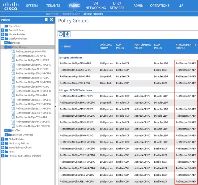
Check each Interface Policy Group, and most particularly, make sure that it is linked to an Attachable Access Entity Profile (labeled ATTACHED ENTITY PROFILE). Can you spot my deliberate mistake?
FABRIC > ACCESS POLICIES > Global Policies > Attachable Access Entity Profiles > RedNectar:GP-AEP
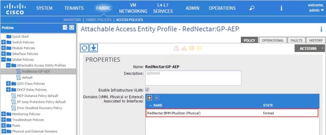
Check that the AEP is linked to the Physical Domain
FABRIC > ACCESS POLICIES > Global Policies > Attachable Access Entity Profiles > RedNectar:GP-AEP | [OPERATIONAL]
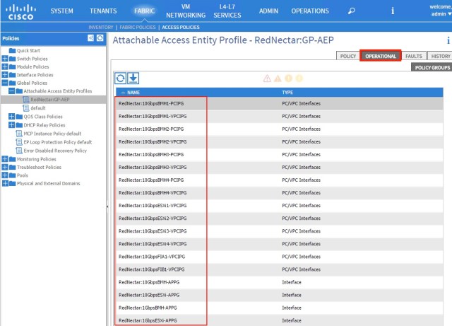
This is a handy place to reverse-check which Interface Policy Groups are linked to this AEP. Can you see that the mistake I pointed out earlier has been fixed?
FABRIC > ACCESS POLICIES > Physical and External Domains > Physical Domains > RedNectar:BMH-PhysDom
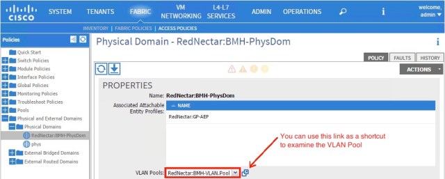
Check that the Domain is linked to a VLAN Pool.
FABRIC > ACCESS POLICIES > Pools > VLAN
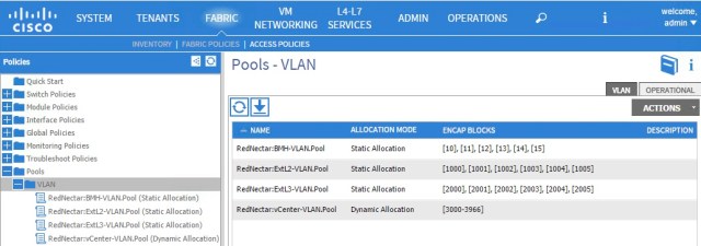
Check that the VLANS are correct for each pool
Step 15: Verify your physical connections
You can check that the physical ports and PC/VPCs are up by going to:
FABRIC > INVENTORY > Pod1 > Leaf1 (Node-101) > Interfaces > Physical Interfaces
FABRIC > INVENTORY > Pod1 > Leaf1 (Node-101) > Interfaces > PC Interfaces
FABRIC > INVENTORY > Pod1 > Leaf1 (Node-101) > Interfaces > VPC Interfaces
FABRIC > INVENTORY > Pod1 > Leaf1 (Node-102) > Interfaces > Physical Interfaces
FABRIC > INVENTORY > Pod1 > Leaf1 (Node-102) > Interfaces > PC Interfaces
FABRIC > INVENTORY > Pod1 > Leaf1 (Node-102) > Interfaces > VPC Interfaces
Each of these screens will give a summary of the physical state of each port/PC/VPC.
Summary Picture
The illustration below shows a summary of the Access Policies that I have configured so far.

But your configuration is still not complete. Remember when you created EPGs (in Part #2), there was a link to a list of Domains. If you are ready to start Connecting servers to the fabric switches, then continue to the next tutorial where the Domain will be linked to the EPGs, and ports assigned to the EPGs.
Next…
RedNectar
| Note: |
If you would like the author or one of my colleagues to assist with the setup of your ACI installation, contact acimentor@housley.com.au and refer to this article. Housley works mainly around APJC, but are not restricted to this area. |
Footnotes
Attachable Access Entity Profile
| Note: | The Attachable Access Entity Profile object is referred to variously as an Attachable Entity Profile; an Attached Entity Profile; an Access Entity Profile and possibly other terms, but most often is referred to simply as an AEP. Although I struggle with reconciling AEP to mean Attachable Access Entity Profile, I will bow to the common practice and stick with the convention others have put in place before me. Don’t be confused. I was. |
| Note: | Domains are sometimes referred to as Domain Profiles (in EPG configuration and in the help documentation). Don’t confuse them with Bridge Domains, they are entirely different concepts – think of Domains as VLAN Domains and you will be closer to the mark. The use of Domains will come to prominence in parts #5 and #6 of this tutorial. |
Interface Profile and Access Port Selector
| Note: | The Interface Profile object is referred to as an associated Interface Selector Profile or Interface Select Profile on the Switch Profile page. On the other hand, the Access Port Selector object is also referred to in various places as Interface Selector or the Host Port Selector. Don’t be confused. I was. |
| Note: | The Switch Profile object is referred to as a Node Profile on the Switch Profile help page. |

Hi Chris,
These are really great tutorials for beginners like me to understand ACI objects, naming schemes, how these objects are tying together and flow of different objects and policies. Really appreciate your effort.
Although I know it has been very late, but Is there any chance you’ll post Part 5 and 6, it’ll be great help for people like me who are beginning their journey in ACI.
Faisal,
I made a note on my “to do for 2025” to update these tutorials to take into account of the simplifications brought about by ACI v 5.2g. Hopefully I’ll get around to doing that soon, and there’s a good chance that I’ll continue with a few more tutorials.
Pingback: Cisco ACI Tutorial 3 – Sing a new song for sorting server groups and policy | RedNectar's Blog
Hi there… most excellent work so far, and hoping for Part 5 also!
Thanks ADam, working on #5…
Hello Chris,
You Cisco ACI tutorial is absolutely the best and I can’t wait for part 5. Are you planning to continue this post?
Thank you!
Alex
Pingback: Cisco ACI Tutorial – A Configuration Guide | RedNectar's Blog