
Cisco ACI Tutorial – A Configuration Guide
2025 Update: Revised and revived in line with newer thinking and ACI v5.2+ updates
Cisco ACI Tutorial – Part 1
Note: |
This is the first of a series of blog posts originally published in 2015. The fundamental principles are the same, but some aspects needed 10 clean out (broken links, new features…) |
If you are new to Cisco Application Centric Infrastructure (ACI) then you may well be daunted at this new method of configuring switches. In this multi-part tutorial, I hope to take some of the configuration pain out of your headache.
I will take you through some of the underlying concepts, but do not attempt to explain the theory of ACI, such as VXLAN overlays and the like.
Objective
This is a configuration tutorial. It takes you through the steps needed to configure a sample ACI fabric. The journey will give you important foundations in naming conventions that will help you understand your configuration in the future, and establish some best practices and conventions that will guide you long into the future.
At the completion of the tutorial, you will have a fully configured ACI fabric ready for testing. You are responsible for making sure that all systems are production ready before deployment in a live network.
Prerequisite
To get the most out of this tutorial, you will need some basic understanding of Cisco ACI and the role of the Application Policy Infrastructure Controller (APIC). Ideally, you will have access to an APIC and an ACI fabric, or the ACI Simulator. With even just a Github or Google login, you’ll be able to access the Cisco DevNet site and locate the ACI Simulator sandboxes where you can practice all the configuration steps in these tutorials.
Cisco partners/customers with sufficient rights to their CCO login, will also be able to get access to an ACI simulator for a few hours at a time by logging on to Cisco dcloud.
If you are not comfortable with terms like Leaf, Spine, topology, End Point Groups and Application Profiles, then you will do well to do some research before you begin. I’d recommend the following:
- This CBT Nuggets video is one of the better summaries and takes just over fifteen minutes. [Please start with this one]
- Roger Perkin covers much the same material in this 11:33 min video
- Cisco Live presentation BRKACI-1601 – Introduction to ACI the first two sections (Fabric Basics and ACU Policy Model Simplified) anyway.
- The Cisco Operating Application Centric Infrastructure publication. [Highly Recommended]
- The ACI Fundamentals Guide – about 322 pages if you download the .pdf copy.
- Read the APIC Getting Started Guide. this link and the previous are linked to ACI v6.x – if you are reading this in the future, you may need to search for later versions of the same references.
Let’s Begin
Assumption
To get the ball rolling, I will assume that:
- Your ACI devices are racked and stacked, and cabled according to the Topology below
- You have completed the assigned Out of Band (OOB) Management IP addresses to your APIC(s) and assigned addresses to the TEP pool as described in the “Setting up the APIC” section of the APIC Getting Started Guide.
- You have a management station logged into the APIC GUI ready to begin configuring your ACI fabric.
TIP: |
If you have real lab equipment (rather than using a simulator), then you will also be able to physically test your configuration if you have:
|
Structure
This tutorial has seven parts, including this one.
- Let’s Begin
- That’s this first tutorial where I cover the topology I will use, the Lab setup and conventions.
- Goodbye to VLANs. Well… not quite
- Tenants, VRFs, Bridge Domains and Subnets
- Sing a new song for sorting server groups and policy
- Application Profiles, End Point Groups and Contracts
- TheAccess Policy Chain – a new “interface range” command
- Access Port Profiles and Interface Profiles
- And all that goes with it (Interface Policies, Policy Groups…)
The Topology
You probably know that an ACI Topology consists of at least two Leaf and two Spine switches and three APICs. For this tutorial, I will use a typical lab environment which has just one APIC and one Spine switch, although in truth spine switches don’t feature at all in the configuration. What will be more important is the equipment that is connected to the leaf switches. In my lab, this is a L2 Switch with two hosts attached, and two more hosts connected directly to the leaf switches.
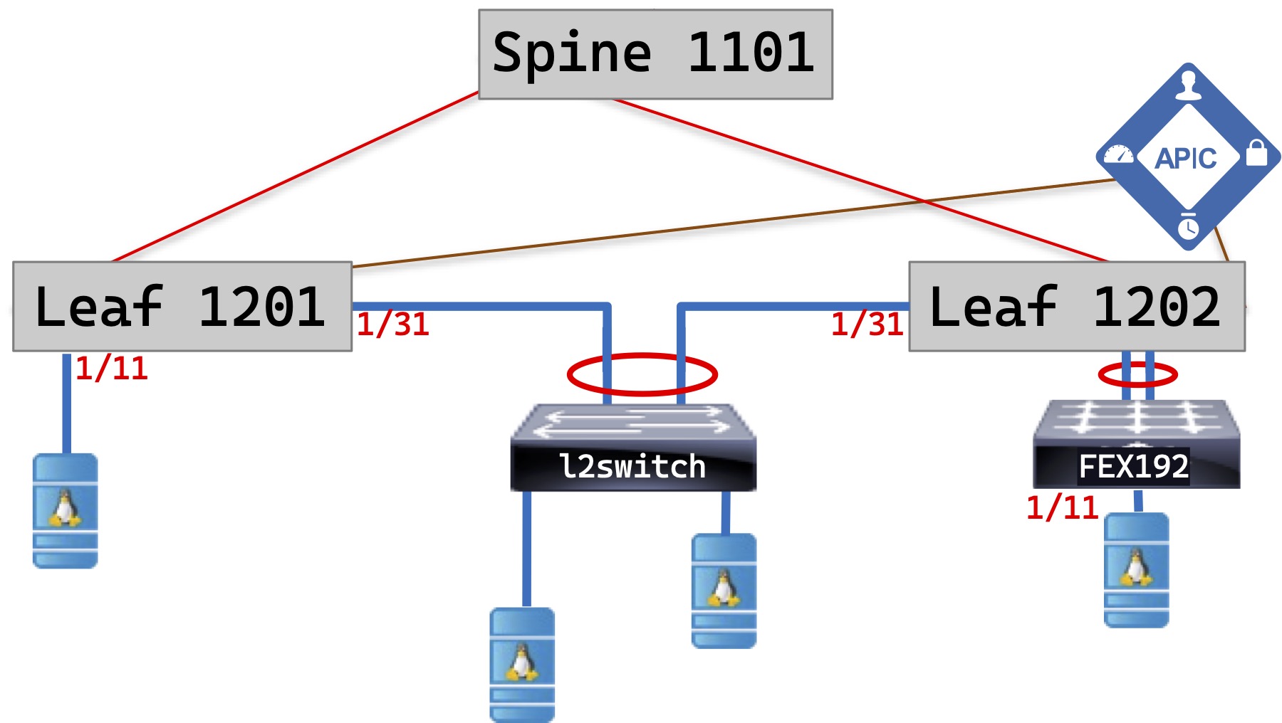
ACI Topology
Note that there are two leaves. There is also a FEX attached which you probably don’t have, but is included so I can make this tutorial a little more comprehensive. To make life simple, I am going to use the following ports on each leaf switch for the following purposes:
| Port range | Use |
| 1/1-8 | Infrastructure use – APICs, FEXes, future IPN/ISN etc |
| 1/9 | Common DNS Server |
| 1/10 | Eternal Router |
| 1/11-28 | Single Attached Hosts (Bare Metal or Hypervisor) |
| 1/29-30 | SPAN Ports |
| 1/31-48 | VPCs |
| 1/49-54 | Uplinks to Spine |
I will refer back to this table in Tutorial #4 All about Access Policies – the new “interface range” command.
The Device Numbering Plan
Before you begin your setup, you’ll need to have a plan of how to number your Leaf and Spine switches – and your FEX devices if you have them.
Device numbers in ACI must be in the range 101-4000. APIC nodes always get get IDs 1-x where x is the number of APICs you have.
RedNectar’s Node numbering schema
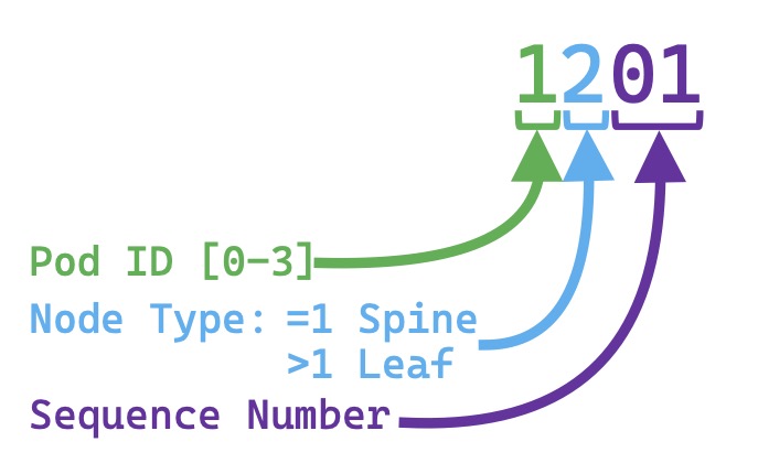
RedNectar’s Node numbering schema
For purposes of planning, it’s useful to be able to distinguish the location of switches in a Multi-Pod environment, so I have chosen the first digit of my switches to be 1 to indicate that it is in Pod 1 – or site 1 – if you are sure they’ll never be another pod, you could use 3 digit Node IDs.
The next digit indicates the level in the hierarchy, with 1 indicating a Spine switch, and higher digits representing a Leaf switch, while the last two digits are a sequence number starting at 01
| TIP: |
While registering Nodes, you’ll only be able identify which node is which by its serial number. If you want certain nodes numbered in a certain way based on rack position or some other criteria, make sure you have a list of serial numbers and your numbering scheme organised before you continue |
The setup
As I mentioned above, I’ll assume you have completed the assigned Out of Band Management IP addresses to your APIC(s) and assigned addresses to the TEP pool as described in the “Setting up the APIC” section of the APIC Getting Started Guide. and can now log into your APIC’s GUI.
Already your fabric has begun the discovery process using LLDP, but before you can continue, you will have to register each leaf and spine switch in the APIC. At the completion of this process, the APIC controllers will discover each other and form an APIC Cluster to become a single management unit.
Conventions
I will refer to menu items in the APIC in the following manner:
Fabric > Inventory >> Pod 1 > Leaf1201
means that you should select the main menu item Fabric, the sub-menu item Inventory then the double >> means you should move to the Navigation pane, expand the Pod 1 branch then select the item Leaf1201. Leaf1201 is in purple italicised print because Leaf1201 is a user assigned name – in your case you may have decided to call it L1201 or something different – so you will have to be on the lookout when menu paths have purple italicised items, if you don’t follow my names exactly, you may have differences.
Menu Bar, Submenu Bar, Navigation Pane and Work Pane
Sometimes, you will need to click in the Work Pane to perform some tasks, and in this case you may find that the work pane has tabs across the top, and possibly another row of tabs under that or even more tabs under that. When you need to click on a tab, the tab name will appear in square brackets after a vertical bar after the item you need to select in the navigation pane, like Fabric > Access Policies >> Policies > Interface > CDP Interface > system-cdp-enabled >| [History] | [Events] , which says, “After you have selected Fabric > Access Policies in the Menu and Submenu bars, expand Policies in the navigation pane, and continue expanding the Interface, then CPD Interface and select the system-cdp-enabled object. The >| sequence means the next item will be found in the Work Pane, so select the History tab in the Work Pane then select the tab under that called Events.
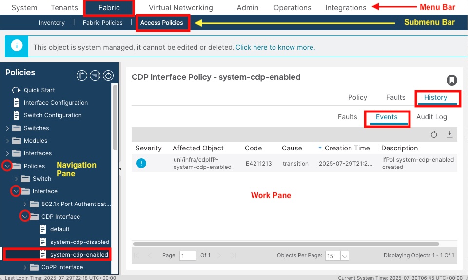
ACI GUI Navigation
Configuration Steps
| Note: |
If you are using the Cisco DevNet sandbox or Cisco dcloud, you will find that these steps have already been completed. You can go straight to the next tutorial. |
When you first navigate to the APIC GUI, you’ll eventually end up at a setup wizard, with the first item on the page being Fabric Membership
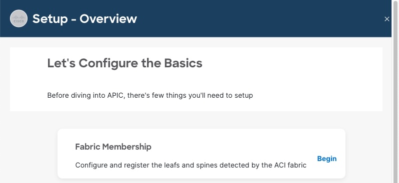
Setup Fabric Membership
Step 1: Register the first leaf node
Click on Begin to start the wizard.
You should see one item in a list with a Node ID of 0, and a Role of Leaf. This device is the Leaf switch that your APIC is connected to.
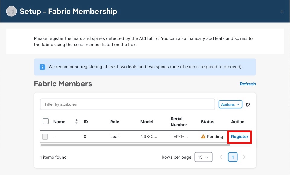
Setup Wizard Nodes List
Under the Action column is an option to Register this node. Click Register and fill in these details:
- Node ID: 1201
- Name: Leaf1201
- Click OK
| Note: |
Any text you have to enter will be shown in bold italics. Items that you have to select from a list or click on will be shown in bold only. |
After clicking OK, you’ll have to keep hitting Refresh until the next device is found, which can take some time, but for the purposes of this tutorial, I’m going to suggest that you leave the Wizard (click Back To Overview, then close the wizard by clicking the x in the top right-hand corner) and continue using the normal GUI so you learn where all these configuration items live should you wish to visit them in the future.
You can use this method also if the Wizard does not start.
| Geek Time Out: |
What has happened so far is this:
This helps explain why it takes a while between the time you enter the switch ID and the time the next switch appears as a Node Pending Registration |
Step 2: Register the spine node
Navigate to Fabric > Inventory >> Fabric Membership >| [Nodes Pending Registration]
You should see another item in the list with a Node ID of 0, Node Type of Spine but no Name. Assuming you registered the first leaf switch using the wizard, this device will be the Spine switch.
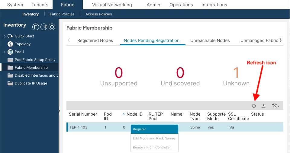
Nodes Pending Registration List in GUI
| Note: |
The field called Role when using the wizard is shown as Node Type here. The one thing you can be sure of about consistency in the ACI GUI is inconsistency |
Right-click on this entry and select Register:
- Node ID: 1101
- Node Name: Spine1101
- Click Register
Step 3: Register remaining node
You can click on the circular refresh icon to encourage the next leaf to appear. When it does, register it with:
- Node ID: 1202
- Node Name: Leaf1202
- Click Register
If you have more nodes to register, continue the process until all nodes are registered
Step 4: Verify your config
Verify your configuration by navigating to Fabric > Inventory >> Fabric Membership >| [Registered Nodes]
You should see that each switch has been given an IP that has come from the range of TEP addresses you gave the APIC in the initial setup, and that the Status shows Active

Registered Nodes Validation
Assuming all is well, it is time to get ready to say Goodbye to VLANs. Well… not quite
RedNectar

Pingback: Cisco ACI Tutorial 3 – Sing a new song for sorting server groups and policy | RedNectar's Blog
Pingback: Cisco ACI Tutorial 2 – Goodbye to VLANs. Well… not quite | RedNectar's Blog
Pingback: Cisco ACI Tutorial 2 – Goodbye to VLANs. Well… not quite | RedNectar's Blog