
Sing a new song for sorting server groups and policy
2025 Update: Revised and revived in line with newer thinking and ACI v5.2+ updates
Cisco ACI Tutorial – Part 3
If you have been responsible for defining groups of servers and devices to which policy can be applied, you have probably used structures called Access Control Lists, or ACLs.
ACLs are typically based on IP addresses and IP address ranges, with added refinements for UDP/TCP port numbers.
ACI has no concept of ACLs. In this part of the tutorial I’ll explain how ACI uses the concept of Application Profiles (APs) and End Point Groups (EPGs) to identify devices and policy groupings. Later I will add Contracts and Filters to complete the story, but for now I want to relate these new concepts to the picture I presented in the previous tutorial.
TIP: |
If you have not read Cisco ACI Tutorial – Part #1, now would be a good time. It contains a diagram of the topology and some important notes about conventions used. Similarly, you will get more familiar with the context of this tutorial if you also take a look at Cisco ACI Tutorial – Part #2 |
The following diagram adds the relationship between Application Profiles, End Point Groups (EPGs), and Bridge Domains to the diagram from Part #2.

Application Profiles and EPGs generic example
EPGs are children of the Application Profile and an Application Profile is a child of the Tenant. The Tenant owns the Application Profile and the Application Profile owns the EPGs. But each EPG must be linked to a Bridge Domain. And here’s the catch. The Bridged Domain that the EPG is is linked to doesn’t have to belong to the same Tenant as the EPG itself – it could belong to the special common tenant.
Application Profiles (APs from now on) are fairly unimportant, so are shown only faintly in the diagram to show about their only purpose. To allow you to have more than one EPG with the same name in the same Tenant – such as the Clients_EPG in the diagram above.
Also in the diagram above, you can see that each AP has two EPGs. The AP and all its EPGs then belong to the Tenant called RedNectar, but the EPG called SharedServices_EPG is linked to a BD in the common tenant. The common tenant is a special tenant where shared configuration can be defined. I have used this relationship here just to illustrate that there is a little chink in the hierarchical model, in that entities that are linked rather than related (parent-child) can be linked outside the parent-child relationship. This structure is rarely implemented in this way, and for the rest of the tutorial I’ll stick to best practices which would certainly NOT link an EPG to a BD in the common tenant.
As far as IP addressing goes, devices in the Clients_EPG from AP2 could be in either the 203.0.113.0/24 subnet, or the 10.1.4.0/24 subnet. Traffic between devices on the 203.0.113.0/24 subnet will be bridged in the normal way (.i.e based on MAC addresses), but traffic between 203.0.113.0/24 devices and 10.1.4.0/24 devices will be routed freely (remember there is NO restriction between devices in the same EPG) without policy applied.
Key Point: |
End Point Groups are basic unit of policy enforcement. End Points (=something with an IP address) within the same EPG can communicate freely without restrictions – ping each other, share files… Later I will show how a Contract is needed to permit devices in different EPGs to communicate. |
However the more interesting arrangement above concerns the two EPGs linked to the InternalClients_BD. Note that there are two EPGs but only one subnet. This means that some End Points that are on the same subnet will NOT be able to freely communicate with each other – they will need a Contract to be able to communicate.
Time out – re read that last paragraph
Yes – it says that you can easily configure different communication policies between devices on the same subnet. Something that would involve tedious editing of MAC address ACLs or PACLs (Port Access Control Lists) in a traditional environment.
The result is something akin to what you might have used Cisco’s Private VLANs for in the past – each End Point uses the same default gateway IP address, but only End Points in the same EPG can communicate freely.
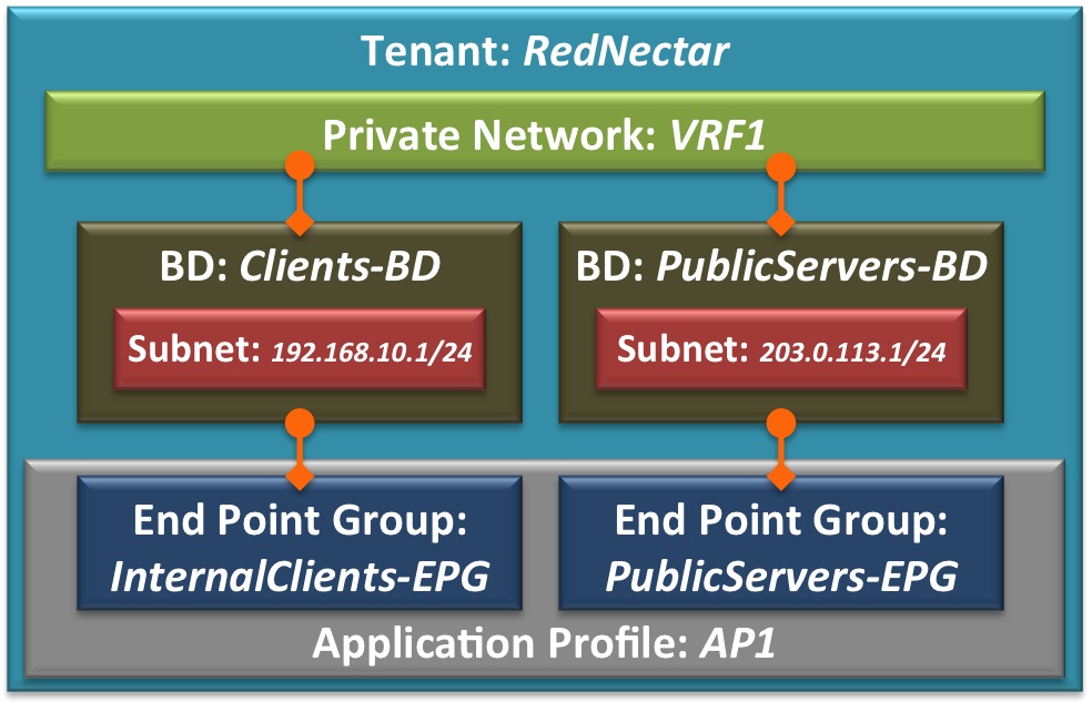
For our configuration model I won’t make it as sophisticated as the diagram. I will simply start by configuring an AP with two EPGs in our existing RedNectar tenant.

Tenant RedNectar with VRF, BDs and Subnets, Application Profile and EPGs
Note the naming used for the EPGs. It is no accident that they closely relate to the BDs that they are linked to. It is possible to have multiple EPGs linked to a single BD (as in the example at the top of this post), but unless you are specifically attempting fine grained separation, I wouldn’t recommend having more than one EPG linked to a BD. This is sometimes referred to a Network Centric design.
The EPG is the atomic unit for applying policy. All devices in the same EPG therefore have unrestricted access to each other, but for traffic to travel between EPGs there will need to be a Contract.
Configuration Steps
For our example, I will begin by creating one Application Profile (AP), and two End Point Groups (EPGs) within the AP. The following diagram shows the expanded model of the tenant RedNectar
Step 1: Add a new Application Profile
Application profiles define the policies, services and relationships between End Point Groups (EPGs).Each application profile contains one or more EPG that can communicate with the other EPGs in the same application profile and with EPGs in other application profiles according to the contract rules. [From ACI online help – Cisco removed online help in ACI v5.2(6)- I’ve attempted to correct this definition where necessary]The Application Profile is a container object for End Point Groups. An Application Profile can also be used to limit the scope of a Contract. [RedNectar’s Definition]
Tenants > RedNectar >> RedNectar > Application Profiles >+ Create Application Profile
| The sequence >+ in the line above means right-click and select |
-
- Name: ProdServers_AP
Step 2: Add two new Application End Point Groups
An EPG is a managed object that is a named logical entity that contains a collection of endpoints. Endpoints are devices that are connected to the network directly or indirectly. They have an address (identity), a location, attributes (such as version or patch level), and can be physical or virtual. EPGs are fully decoupled from the physical and logical topology. Endpoint examples include servers, virtual machines, network-attached storage, or clients on the Internet. Endpoint membership in an EPG can be dynamic or static.
EPGs contain endpoints that have common policy requirements such as security, virtual machine mobility (VMM), QoS, or Layer 4 to Layer 7 services. Rather than configure and manage endpoints individually, they are placed in an EPG and are managed as a group. [Abridged version from ACI online help – Cisco removed online help in ACI v5.2(6)]
An End Point Group (EPG) is a group of End Points that require common services and policies, such a server farm. End Points are defined by IP and/or MAC addresses. End Point Groups must be associated with a single Bridge Domain to enable Layer 2/3 connectivity, and End Point Groups must be associated with at least one (VLAN) Domain, either a Physical Domain or a VMM Domain so that the ACI Fabric can detect incoming traffic from an End Point.
The ACI Fabric uses 802.1Q VLAN tags (or VXLAN VNIDs) to identify which EPG incoming traffic is associated with. [RedNectar’s Definition]
TENANTS > RedNectar > Tenant RedNectar > Application Profiles > AP1 > Application EPGs
Tenants > RedNectar >> RedNectar > Networking > Application Profiles > ProdServers_AP >+ Create Application EPG
-
- Name: AppServers_EPG
- Bridge Domain: AppServers_BD
| TIP: |
Take note of the fact that there is a section in the EPG configuration where you can associate the EPG to a list of Domains(*). Domains play a very important role in the EPG as you will see in part #5 of this Tutorial. |
… >+ Create Application EPG
-
- Name: WebServers_EPG
- Bridge Domain: WebServers_BD
Diagrammatically, you have built what we set out to build:
Tenant RedNectar with VRF, BDs and Subnets, Application Profile and EPGs
Filters, Subjects and Contracts
Before you can apply policy to traffic flowing between EPGs, you will need to create the Contracts that define the policy to be applied. And since Contracts have Subjects and Subjects are linked to Filters, you will need to define those too.
The following diagram shows the relationship between EPGs, Contracts, Subjects and Filters.
Note: |
Note particularly the direction of the arrows, from a provider to a consumer. This convention has upset so many networking professionals (because the first TCP SYN packet will always go from consumer to provider) that they refuse to draw the arrows using the ACI convention |

Structure of a Contract
Filters are easy to understand. A filter simply allows traffic on a particular UDP/TCP port (or traffic on a particular protocol like ICMP). So in my example I have one filter called HTTP_Fltr with two entries – one I have named TCP80 which filters on destination TCP port 80, the other named UDP80, which filters on destination UDP port 80. Another filter is called HTTPS_Fltr with only one entry – TCP443. No prizes for guessing how that naming scheme works!
However, I would like to point out that there is a subtle difference between the two filters. Filters are defined within a Tenant space, so I have defined the first one in the tenant RedNectar. The other one is defined within the common tenant which means they will be available to all tenants.
| TIP: |
Having a collection of useful filters in the common tenant is a great way of saving time and ensuring consistency throughout the system |
Now Contracts are not directly linked to Filters. Instead, Cisco has added an extra layer of flexibility (and complexity) by giving Contracts a child object called a Subject. And it is the Subjects that are linked to Filters – in my example the Contract WebServices_Ct has two Subjects and one of those subjects (WebServices_Subj1) is linked to a Filter that has two entries, while the other Subject (WebServices_Subj2) is linked to a Filter in the common tenant
| Note: |
Mostly contracts have only one subject. The only time you really need a 2nd subject in a contract is when you are implementing a different behaviour for some of the traffic in a traffic. For instance, if I wanted the HTTPS traffic in my example contract above to be offloaded to an SSL offloader, then I’d need to add the second subject to facilitate this. |
The most confusing aspect of contracts is the way policy is applied through the Contract. For a Contract to pass traffic, the EPG either has to Consume or Provide a Contract. and every Contract must have at least one consumer and one provider to be of any use. Notice how the name of the contract indicates the provider of the service. I’ve found that including the word Service in the contract name helps crystallise in the user’s mind the direction that the contract must be applied.
One more aspect of contracts to consider is the contract scope. This can be set to Application Profile, VRF, Tenant or Global, the default being VRF. If the scope is set to anything more restrictive than Global, then, just like filters, contracts can be defined in the common tenant and used by different tenants/VRFs without traffic leaking between the tenants/VRFs.
And finally, in the subject of a contract, you’ll find two utterly confusing options:
Apply Both Directions, and Reverse Filter Ports. I’ve discussed these confusing options in a post on the Cisco Community forum (which I encourage you to join) but for now, I’m going to assume that both options are set and strongly suggest you leave them like that!!!
For my RedNectar example, I will simply assume that the application servers are providing a service on TCP Port 5000 that is consumed by the web servers. This means I need a filter that filters TCP SYN packet on port destination 5000, and allows the return traffic on TCP source port 5000. Luckily, ACI has a neat way of allowing me to create just the forward filter (from consumer to provider – no wonder people are confused about the provider-to-consumer arrows) and using it to filter in both directions. (Have you already guessed that it the two options I mentioned in the last paragraph?)
Once the filter is created, I’ll need a contract that uses it, and finally I’ll need to apply it so the AppServers_EPG is the provider, and the WebServers_EPG is the consumer.
Things always look clearer with a picture.

Contract for AppServers providing a service to WebServers
Configuration Steps
Step 3: Examine pre-defined Filters
A filter policy is a group of resolvable filter entries. Each filter entry is a combination of network traffic criteria, similar to an Access Control List (ACL) [From ACI online help – Cisco removed online help in ACI v5.2(6)]
Filters are a collection of one or more protocol definitions that can be used to block or permit traffic via an ACI contract. Filters can be based on L2 (Ethertype) L3 protocol (IP/IPv6) or IP/IPv6 protocol (ICMP/UDP/TCP). Filters based on UDP or TCP can extend to destination port numbers (and rearely, source port numbers) [RedNectar’s Definition]
Tenants > common >> common > Contracts > Filters
- Note that there are a set of pre-defined filters defined in the common Tenant. These filter can be linked to any Subject in any Contract in any other Tenant.
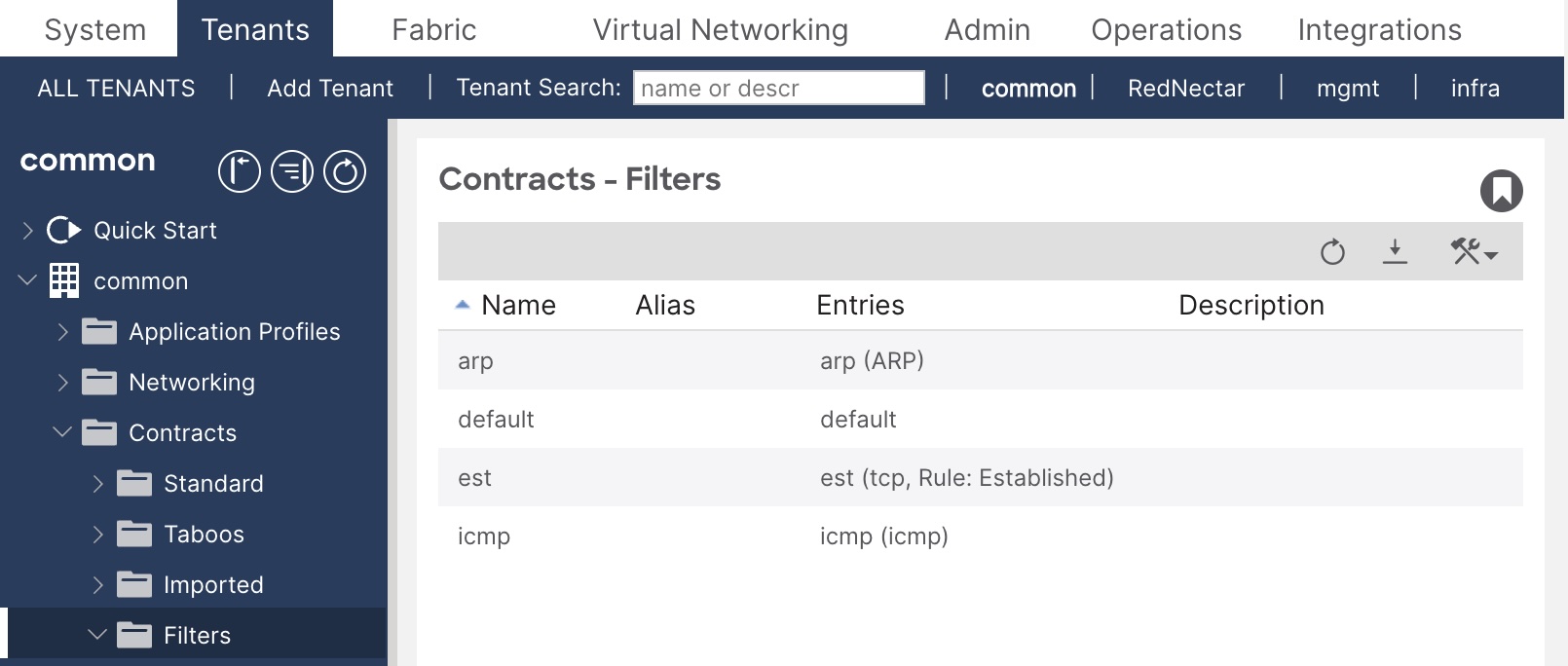
Pre-defined filters in the common tenant
Step 4: Create a common Filter for web traffic
Tenants > common >> common > Contracts > Filters >+ Create Filter
-
- Name: TCP5000_Fltr
- Add (+) Entries:
- Name: TCP5000
EtherType: IP
IP Protocol: tcp
Stateful: [x] Checked
Source Port Range From: any To: any [See Note below]
Destination Port Range From: 5000 To: 5000
- Name: TCP5000
TIP: |
It is tricky entering numbers in the port range fields. Type quickly and hit Tab as soon as you have finished typing. |
Step 5: Create a Contract for this TCP port 5000 traffic
A contract is a logical container for the subjects which contain the filters that govern the rules for communication between endpoint groups (EPGs). Without a contract, the default forwarding policy is to not allow any communication between EPGs but all communication within an EPG is allowed.
A subject is a container for a set of filters, used by a Contract to define how EPGs can communicate. [Adapted from ACI Help]
Tenants > RedNectar >> RedNectar > Contracts > Standard >+ Create Contract
| Note: |
Contracts, like filters, if defined in the common tenant can be used by any other tenant without risk of traffic leaking between tenants. So the contract could be created in the common tenant to make it more globally available, in which case the step would be Tenants > common >> common > Contracts > Standard >+ Create Contract |
-
- Name: AppServices_Ct
- Scope: VRF
- Add (+) Subjects:
- Name: Subj1
- Apply Both Directions [x]
- Reverse Filter Ports [x]
- Add (+) Filters
- Name: TCP5000_Fltr
Consuming and Providing Contracts
Now that you have all of the building blocks – EPGs, Filters and Contracts defined, you can start defining how policy is to be applied to allow traffic between our EPGs. To do this, you will return to the EPGs you created earlier, and link the contract in a provider-consumer relationship. The AppServices_Ct contract will be be linked as a provided contract to the AppServers_EPG and as a consumed contract to the WebServers_EPG. This will allow devices in the AppServers_EPG to ask for TCP services on port 5000. Return traffic will be allowed because the Apply Both Directions and Reverse Filter Ports options were set in the subject of the contract.
| Note: |
The Apply Both Directions and Reverse Filter Ports options cause a lot of confusion, and is one of the most mis-understood concepts in ACI. You can learn more about these options if you read the answer I gave to a question on the Cisco ACI community forum. |
Configuration Steps
Step 6: Link EPGs with contacts in their appropriate consumer-provider relationship.
Tenants > RedNectar >> RedNectar > Application Profiles > ProdServers_AP > Application EPGs > AppServers_EPG > Contracts >+ Add Provided Contract
-
- Contract: AppServices_Ct
Tenants > RedNectar >> RedNectar > Application Profiles > ProdServers_AP > Application EPGs > WebServers_EPG > Contracts >+ Add Consumed Contract
-
- Contract: AppServices_Ct
Step 7: Verify your configuration
Tenants > RedNectar >> RedNectar > Contracts > Standard > ProdServers_AP >| [Topology]
You should see icons representing your EPGs and your Contracts. Note that the arrows show the direction from Provider to Consumer. You can move these icons around, and without too much trouble, you should be able to get your screen looking something like this:

Topology for AppServices_Ct contract
| TIP: |
You can get a similar (and more complete when multiple contracts are involved) by navigating to:
Tenants > RedNectar >> RedNectar > Application Profiles > AppServices_Ct >| [Topology] |
Tenants > RedNectar >> RedNectar > Application Profiles > ProdServers_AP > Application EPGs > AppServers_EPG >| [Operational] | [Contracts]

AppServer_EPG Contracts view – not all columns shown
Note that two filters are produced when you create contract – this relates back to those Apply in Both Directions and Reverse Filter Ports options! But the really weird thing is that even though the AppServers_EPG is the provider of the contract, in this view, it is shown as the consumer. I have no idea behind the reverse logic of this view, but what is useful is that you see the those two filters that were actually created even though you actually only associated one filter with the contract.
Discussion
You now have policies in place to control traffic between devices in the two EPGs you have created. But at the moment there is absolutely no use for your AP, your EPGs or any other policy related configuration that you have completed, because you have yet to tell the APIC which connected devices and servers belong to which EPG.
And before you can do that, you will have to tell the APIC how to identify traffic and on which interfaces to expect traffic for these EPGs.
And to do that you will need to learn all about the Access Policy Chain – a new “interface range” command.
Next…
RedNectar
Footnotes
| Note: | Domains are sometimes referred to as Domain Profiles (in EPG configuration and in the help documentation). Don’t confuse them with Bridge Domains, they are entirely different concepts – think of Domains as VLAN Domains and you will be closer to the mark. The use of Domains will come to prominence in parts #5 and #6 of this tutorial. |

Pingback: Cisco ACI Tutorial 4 – All about Access Policies – the new “interface range” command | RedNectar's Blog
Pingback: Cisco ACI Tutorial – A Configuration Guide | RedNectar's Blog
Pingback: Cisco ACI Tutorial 2 – Goodbye to VLANs. Well… not quite | RedNectar's Blog